In recent years, due to the popularity of portable products, such as smart phones, tablets, laptops, MP3 players, etc., almost everyone uses these portable products, but when you are away from home, you are using a smartphone to make a phone call or use a tablet to watch In the film, the battery suddenly lost power, and often makes people feel very helpless. In order to avoid the situation when the smartphone or tablet is out of power when going out, the Power Bank is almost a must-have accessory for these portable products. At the same time, with the rapid development of related technologies of lithium ion batteries, the battery capacity of the mobile power source is getting larger and larger, but the volume is not increased and decreased, which greatly improves the convenience of carrying the mobile power source.
At present, in addition to the pursuit of ever-increasing battery capacity and the possibility of being thin and light, the mobile power itself has a long time to charge and a total amount of power that can be released, which is also a concern for consumers. Therefore, how to design a mobile power circuit with short charging time and high conversion efficiency is also an important issue in the design of mobile power products. In view of this, this article will explain how to implement a small, efficient mobile power circuit.


Circuit scheme
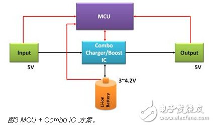
At present, the circuit scheme of the mobile power supply can be roughly divided into three types. The first scheme is Charger IC + Boost IC. This scheme uses the Charger IC to charge the lithium battery of the mobile power source, and the Boost IC discharges the mobile device, as shown in FIG. Show. The second solution is MCU + Charger IC + Boost IC. In addition to the part of the first scheme, the MCU detects the lithium battery and the input and output voltage. This scheme is relatively common, as shown in Figure 2. The third option is MCU + Combo IC. This solution integrates Charger IC and Boost IC into one IC, which can reduce the number of parts and save PCB space, as shown in Figure 3. This article will give a detailed introduction to the second most common solution.
Mobile power circuit
In recent years, as portable products continue to grow, the demand for mobile power supplies continues to increase. Lightweight, compact, fast charging, high conversion efficiency and high security have become the primary considerations for consumers when purchasing mobile power. Demand, many companies have launched mobile power solutions, here we use the AIC6511 and AIC3420 developed by Peiheng Semiconductor as a design example for readers' reference.
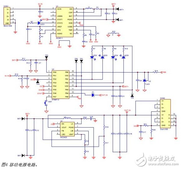
As you can see from the previous section, a complete mobile power circuit includes a battery charge management IC, a boost converter IC, and an MCU. Each part affects the overall performance of the mobile power supply, so it is important to select the appropriate IC. Figure 4 shows the mobile power circuit to be introduced in this paper. It is mainly composed of AIC6511 lithium-ion battery charge converter, AIC3420 boost converter and MCU. The proposed mobile power circuit will be described in detail below.

A. Lithium-ion battery charge converter
Lithium-ion battery is currently the most widely used rechargeable battery. It can be used for low-power products with single lithium batteries. It can also connect multiple lithium batteries in series to obtain higher voltage and capacity. For example, mobile power is more than one. Lithium batteries are connected in parallel to achieve high capacity. Lithium batteries have the advantages of high energy density, low self-discharge rate, no memory effect, long life and light weight, and are very suitable as power sources for portable products.
Lithium battery charging ICs are divided into linear and switching types. The cost of linear charging ICs is low, and the number of IC pins is small, requiring only a few passive components. However, the linear charging IC has a large power loss. If the design is not good, the IC temperature is too high, and most of the mobile power supplies generally use a poorly heat-dissipating plastic case, so that the linear charging IC cannot provide a large charging current. Linear charging ICs are generally suitable for low-capacity lithium-ion battery applications. If you want to fully charge the battery within a short period of time, you must increase the charging current. Consider using a switched charging IC. The switching charging IC utilizes high-frequency switching of the switch to achieve energy transfer, provides a large charging current, and has high conversion efficiency without overheating, and is suitable for charging applications of high-capacity batteries.
During the charging process, when the battery voltage rises to 4.2V, stop charging immediately to avoid danger caused by overcharging the battery. When the battery is discharged, if the battery voltage drops below 2.5V, stop discharging immediately to avoid the battery passing. Reduce the battery life. In addition, the lithium battery is also applied with a short-circuit protection circuit to prevent the lithium battery from being dangerous due to a short circuit.
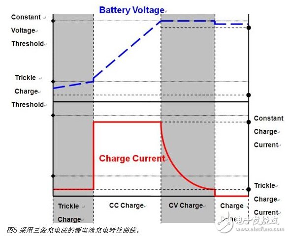
Lithium batteries have high requirements for charging, and require precise charging circuits to ensure the safety of charging. In particular, it is required to terminate the charging voltage within ±0.5% of the rated value. At present, lithium battery charging is most commonly carried out by a three-stage charging method, namely, a Trickle Charge Mode, a Constant Current Charge Mode, and a Constant Voltage Charge Mode. The charging IC will detect the state of the battery before charging. If the battery voltage is greater than 3V, it will be charged in the constant current charging mode; if the battery voltage is lower than 3V, it will be in the pre-charging mode (about 10% of the constant current charging mode charging current) Charging, when the voltage is close to the end voltage, it is changed to constant voltage mode charging. At this time, the battery voltage is almost unchanged, but the charging current will continue to decrease. When the charging current drops to a certain value (about 10% of the constant current charging mode charging current) ), the charging current will be turned off and the charging is completed. Figure 5 shows the charging characteristics of a lithium battery using a three-stage charging method.

B. Lithium-ion battery charge converter
The AIC6511 is a highly integrated switched Li-Ion battery charge management IC with high precision current and voltage regulation. It is suitable for charging applications in single lithium batteries. When the battery voltage is close to the input voltage, it will enter the duty cycle. The 100% mode of operation continues to charge the battery, and its own switching frequency of up to 1.6MHz will help reduce the size of external parts. In addition, it also provides charging status indication and battery removal detection mechanism. It supports USB mode and AC Adapter mode. It can output up to 2A of charging current. The charging current can be determined by external resistor. The Trickle Charge Current can be calculated by the following formula:

The Trickle Charge Current can be calculated by the following formula

The Constant Current Charge Current can be calculated by the following formula:

Constant Current Charge Current can be calculated by the following formula

When using USB power as input, the input current can be limited so that the input current can be lower than the current provided by the USB power supply, and the USB power supply can be prevented from entering the overcurrent protection. The input current limit setting value is calculated as follows:

The input current limit setting value is calculated as follows
In addition, the Safety Timer (Safety TImer) avoids the danger of excessive charging time due to battery damage. As long as the charging time reaches the set safe time, even if the battery has not reached the termination voltage, the charging IC will turn off the charging current and stop charging. The safety timing can be set by capacitor C5. The safe timing in Trickle Charge mode can be calculated by the following formula:
The safe timing time in the Trickle Charge mode can be calculated by the following formula
The safe timing time in Constant Current Charge mode can be calculated by the following formula:
The safe timing time in Constant Current Charge mode can be calculated by the following formula
In order to avoid high-temperature battery charging and improve safety, the IC detects the battery temperature through a negative temperature coefficient (NTC, NegaTIve Temperature Coefficient) thermistor. When the temperature is too high or too low, the IC will immediately terminate charging. The battery is charged when the battery temperature is maintained within a safe range (usually 0 to 45 °C). In order to prevent the battery from discharging to the input, the built-in Sleep Mode function, when the input voltage is lower than the battery voltage, the P-channel MOSFET Power Switch will be turned off to prevent the battery from discharging the charging IC or the input. .
In addition, Short Circuit ProtecTIon function, Over Current ProtecTIon function and Over Temperature Protection function, when the output is short-circuited, the short-circuit protection function is activated, the inductor current is limited and switched. The frequency will also be reduced to reduce the loss; the IC itself will also detect the current flowing through the internal power switch. When the current of the power switch is too large, the overcurrent protection function is activated, and the current limiting the power switch is no longer increased. Protect the internal switch; in addition, when the IC junction temperature reaches 150oC, the over-temperature protection function will be activated and the IC will stop charging until the IC temperature drops to 120oC before charging resumes.
C. Boost converter and MCU
The AIC3420 is a light-load, high-efficiency synchronous step-up DC-DC converter IC with a minimum input startup voltage of 0.9V. It can be used as a single power supply with a single lithium battery. The maximum output current is 2.1A, which is suitable for large currents. Applications. When the load is operating at light load, the IC will switch to PSM (Pulse Skipping Mode) mode to reduce standby power loss and improve light load efficiency. True Shutdown function, when the IC enters Shutdown mode, the output voltage drops to 0V. The Zero Current Detection function eliminates the inrush current of the inductor current and greatly improves the light load efficiency. The maximum efficiency is 94%, which makes it more efficient for mobile power.
In addition, the Soft Start function limits the overshoot and Inrush Current of the output voltage at startup to avoid damage to the IC and parts. The AIC3420 also has short-circuit protection, over-current protection, over-temperature protection and over-voltage protection.
In the mobile power circuit described in this article, the main functions of the MCU are input voltage detection, output voltage detection, battery power status display, and output overcurrent protection. In the circuit, the LED will display the battery's power, allowing the user to know the battery's power status. When the input and output voltages are too high or too low, the MCU will send a signal to turn off the IC. In addition, when an output overcurrent occurs, the MCU will also turn off the IC to protect the battery and IC.
in conclusion
The booming of portable products has made the functions and specifications of mobile power supplies increasingly improved. Therefore, how to efficiently charge and discharge has become the mainstream of various manufacturers. Since the switching charger is more widely used in linear chargers and has higher conversion efficiency, it is suitable for high-capacity lithium battery applications. Therefore, this paper proposes a mobile power scheme that replaces the linear charging IC with a switched charging IC to increase the charging current, shorten the charging time, and cause the charging circuit to have almost no overheating problem.
For Pixel Glass,Pixel Glass,Google Pixel 4 Xl Glass,Google Pixel 6 Pro Front Glass
Dongguan Jili Electronic Technology Co., Ltd. , https://www.ocasheet.com