In March 2015, Apple's MacBook, Google's Chromebook, July 2015 ASUS Tablet ZenPad, September 2015 Nexus 5X, 6P & Pixel C released and used Type C technology, in addition to these Nokia Z1, LeTV mobile phone and one Plus 2 mobile phones also have Type C functions. The discussion of Type C's topic is getting hotter, which makes us review the future of Type C again.

We first took the NOKIA N1 on the market and the Type C research of LeTV. We found that the type-c mobile phone, although it is a type-c connector, does not meet the specification of type-c. The original factory is equipped with a TYPE-A charger, TYPE- A to type-c cable, so the mobile phone is still an interface concept, watching the mobile phone industry really "Type C" still needs a transition period. But NB's MacBook, Google's Chromebook uses USB-C MulTI-FuncTIon (USB 3.1 Gen1, DP), Type-C charging/PD charging, which is arguably the more authentic Type C. This also shows that the trend of different types of Type C in different industries is different.
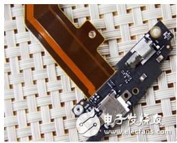
Before talking about Type C technology and the market, we can recognize Type C. First of all, first correct the "tpye C is USB3.1", USB3.1 is the protocol, Tpye C is the interface definition, is a completely different concept.
Type A, Type B, and Type C are as follows:

Type C female definition:

Type C male definition:

What are the advantages of Type C? 1. Support "positive and backward insertion" function that can be inserted from both sides of the front and back; 2. Maximum data transmission speed reaches 10Gbit/s; 3. Can withstand 10,000 times of repeated insertion and removal; 4. Slim design; 5. USB Type CC interface socket end size is about 8.3mm & TImes; 2.5mm; 6. Standard specification cable with USB Type-C connector can pass 3A current, and also supports "USB PD" beyond the existing USB power supply, can provide Maximum 100W of electricity.
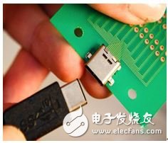
To sum up, Type C does have a lot of advantages. This trend is well-founded. Let's take a look at the market and see how the market will accept Type C. According to different industries, my rough summary: The first fastest login should be a. mobile phone; b. notebook NB; c. charging treasure; d. charger (trip charger, car charger); e. handheld, miniaturized equipment (POS, drone, etc.)
· The reason for choosing them is that there are several points: 1. There is a need to transmit information quickly; 2. There is a need for miniaturization; 3. The charging speed is required. 4. The large market volume is conducive to the development of the Tpye C economic chain.
· Now that the market has begun to infiltrate, online experts predict that 2016 will be a starting point and a popular period.
· If you want to create a Type C standard interface, do not pursue USB3.1 first, so the design is simple and low cost. For example, if the mobile phone is changed to USB Type-C USB2.0 interface, only need to redo the cable, no chip, the cost is very high. small.
If Tpye C is developing smoothly, the following markets will also be popular: a. high-end lighting DC to DC; b. projector; c. security; d. netcom; e. industry; f. medical; g. set-top box.
The reason for choosing them is that 1.Type C supports a maximum of 100W output, and power is sufficient in some interfaces to support the application. 2. These industries need to be standardized and cost-effective. 3. Demand transfer rate is fast and reliability requirements are strong.
· Type C design has provided a lot of solutions for various chip companies, but many of them have left their choices for protection. In this regard, I can focus on talking about protection. It is nothing more than over-current protection.
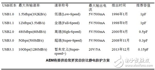
Overvoltage protection, Type C has a lot of signal lines, all need to do static protection. USB Type-C can use two sets to ensure that both positive and negative can be inserted, but in fact, only one set of RX/TX is used for data transmission. The speed has reached 10Gb. If you upgrade the protocol later, the two groups will be the same as DisplayPort 20Gb. So the future trend ESD has lower capacitance requirements (<0.1pF).
Summary of signal line transmission rate and AEM recommended capacitance:
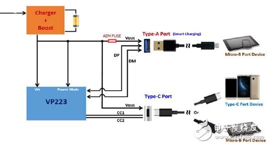
Overcurrent protection, the design of the Type C front end will add power switch, so some USB2.0 does not add fuse. However, due to the large current of Type C, the power of the load is large, and the impact energy caused by the abnormality is destructive. Therefore, the power switch can not completely cover the security of the interface, which requires over-current protection.
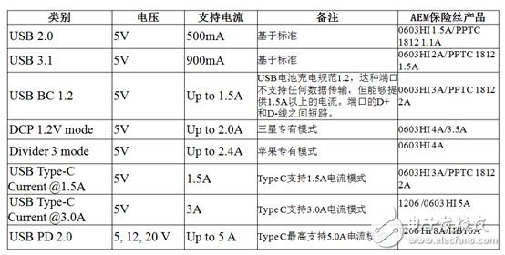
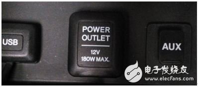
Type C power supply and ground each have 4, so it can support up to 100W. PS to the car car filling port view, found that can support 180W, so car charging after the type C NB charging application is promising. As shown below. USB Type-C supports 20V/5A, which requires additional support for USB PD, so the USB Type-C interface does not necessarily have 20V/5A function.
Of course, the function of type C can also be seen in the definition of pin pin. For example, there are two sets of differential signals of pin/pin TX/RX. CC1 and CC2 are two key pins. The function is to detect the connection, distinguish the front and back, and distinguish DFP ( Downstream Facing Port) and UFP (Upstream Facing Port), configure Vbus (USB Type-C and USB Power Delivery modes), configure Vconn (when there is a chip in the cable, a cc transmission signal, a cc becomes a power supply) Vconn), configure other modes (such as DisplayPort, pcie bus when connecting audio accessories).
DFP (Downstream Facing Port) is also the main, UFP (Upstream Facing Port) is from. In addition to DFP, UFP, and DRP (Dual Role port), DRP can be used as DFP or UFP. When DPR is connected to UFP, DRP is converted to DFP. When DRP is connected to DFP, DRP is converted to UFP. The two DRPs are connected together, at which point either one is DFP and the other is UFP.
Therefore, many small partners in the market reflect that the Nexus 6P is connected to the Nexus 5x type C through type C. It can perform 6p to 5x charging, which is based on the above principle.
Finally, the design suggestions for the type C layout VIA scheme are introduced:
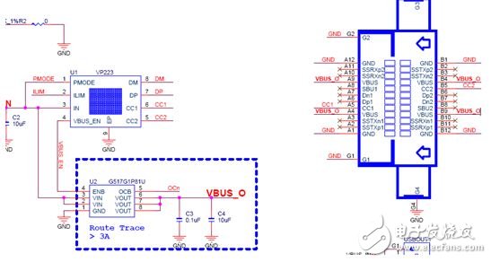
AEM in USB PD 2.0---NB Type C application
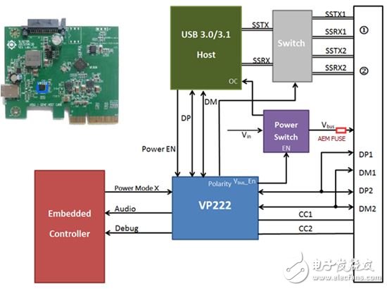
AEM in Netcom, switch Type C application
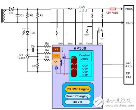
AEM in the charger Type C application
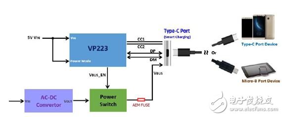
AEM in mobile power charging treasure Type C application
- The Description of 3G 4G LTE/5G Antenna
-
2G base station: GSM: 900/1800MHz; CDMA: 800 MHZ;
3G base station: CDMA2000&WCDMA: 2100MHz; Td-scdma: 1880-1920201 0 0-2025232-2370 MHZ;
4G base station: TDD-LTE: 2320-2370,2570-2620MHz; -
This paper discusses the key technologies in 3G/4G/5G (third generation/fourth generation/fifth generation) communication systems, and then discusses the differences in the antenna technologies adopted by them. After reading and studying a large number of papers on the key technologies of 3G/4G/5G communication system, here I make some analysis and summary of my own. With the rapid development of science and technology, mobile communication technology has undergone profound changes, from 1G to 2G, to 3G, and then to 4G and 5G. On December 4, 2013, the fourth generation of mobile communication 4G technology was officially operated in the Chinese market, which means that China's mobile communication industry has entered the 4G era. At this time, research institutes in various countries and world-renowned enterprises engaged in communication technology research have entered the research and development of the new generation of mobile communications, namely 5G (fifth generation mobile communication system). No matter which generation of communication system, the research technology is to analyze the characteristics of wireless communication channel to overcome the noise interference. A lot of researchers are now looking at Massive MIMO technology. How is it different from the antenna technology used in 3G/4G communication systems? Will it become the core technology of the next generation of wireless communications? 1 Key technologies of 3G/4G/5G Communication System 1.1 Key technologies of 3G Communication System Since the early 1990s, the mobile communication industry began to actively study the standards and technologies of the third generation of mobile communication. In January 2009, China's Ministry of Industry and Information Technology issued 3G licenses to China Mobile, China Telecom and China Unicom, indicating that China entered the ERA of 3G mobile communications. The third generation mobile communication system mainly includes WCDMA, CD-MA2000 and TD-SCDMA. Its key technologies include: A. Rake receiving technology; B. Channel coding and decoding technology; C. Power control technology; D. Multi-user detection technology; E. Smart antenna; F. Software radio. 1.2 Key technologies of 4G Communication System In December 2013, China officially entered the era of 4G (fourth generation mobile communication system) communication network. In 4G mobile communication system, OFDM(Orthogonal frequency Division multiplexing) technology is adopted. OFDM technology is due to its spectrum utilization
3G antenna _5G antenna _14 years antenna manufacturer _ Feiyuxin
14 years focus on antenna research and development, production, sales, 30,000 strength of the factory, 600 people production capacity, the main sucker antenna, glass fiber reinforced plastic antenna view details & GT;
It is widely regarded as high rate of 2 and good anti-multipath fading performance. In the future, RESEARCH related to OFDM technology will also be carried out in 5G communication networks. The main key technologies of 4G communication system include: a. OFDM technology; B. MIMO technology; C. Multi-user detection technology; D. Software radio; E. Smart antenna technology; F. IPv6 technology. China's Ministry of Industry and Information Technology has just issued 4G licenses to the three major operators, and they are still deploying their networks on a large scale with a small number of users. At this time, China Mobile said it will start the RESEARCH and development of 5G communication system. Analysts pointed out that the three major operators are participating in THE RESEARCH and development of 5G, one is to keep up with the changes of The Times, and the other is that the demand is faster than the technology development. Li Zhengmao, vice-president of China Mobile, said at the 2014 MWC in Barcelona: "China Mobile will fully support the development of 5G projects, hoping to lead the industry in THE development of 5G technology and the setting of technical standards." With the deepening of mobile communication technology research, the key support technologies of 5G will be gradually defined and enter the substantive standardization research and formulation stage in the next few years. The jury is still out on what core technologies will be used in the future. However, I have compiled a list of nine key technologies that have been the focus of discussion in various high-end mobile forums. A. Large-scale MIMO technology; B. Filter bank based multi-carrier technology; C. Full duplex technology; D. Ultra-dense heterogeneous network technology; E. Self-organizing network technology; F. Use of high frequency band; G. Software-defined wireless networks; H. Wireless access technology: (1) BDMA (Beam Split multiple Access technology)
5G antenna high-gain antenna [strength team customized on demand]
Yunwei Technology professional provide 5G antenna array antenna microstrip antenna fiberglass antenna Bluetooth antenna uWB antenna car view details & GT;
3 (2) NOMA (Non-orthogonal multiple Access technology) i. D2D (device-to-device) communication. Figure 1 is the layout of Massive MIMO antennas in 5G communication networks. I am studying Massive MIMO technology in my lab. Figure 1 shows users communicating with each other centered on a large-scale antenna. The performance of wireless communication systems is mainly restricted by mobile wireless channels. Wireless channel is very complex, and its modeling has always been a difficult point in system design. Generally, statistics are made according to the measured values of communication systems in specific frequency bands. Wireless fading channel is divided into large scale fading channel model and small scale fading channel model. The so-called large-scale fading model describes the field intensity variation over a long distance (hundreds or thousands of meters) between the transmitter and receiver, and reflects the rule that the received signal power changes with the distance caused by path loss and shadow effect. A small scale fading model describes the rapid fluctuations of the received field intensity over a short distance or time. The large scale fading channel model is caused by the influence of the surface contour (such as mountains, forests, buildings, etc.) between the receiver and the source. The small-scale fading channel model is caused by the multipath effect and doppler effect. If there are a large number of reflected paths but no LOS (direct signal) signal component, the small-scale fading is called Rayleigh fading, and the envelope of the received signal is described statistically by the Rayleigh probability density function. If LOS is present, the envelope is subject to Rician distribution. Multipath effect phenomena cause flat fading and frequency selective fading.
The Picture of 3G 4G LTE/5G Antenna
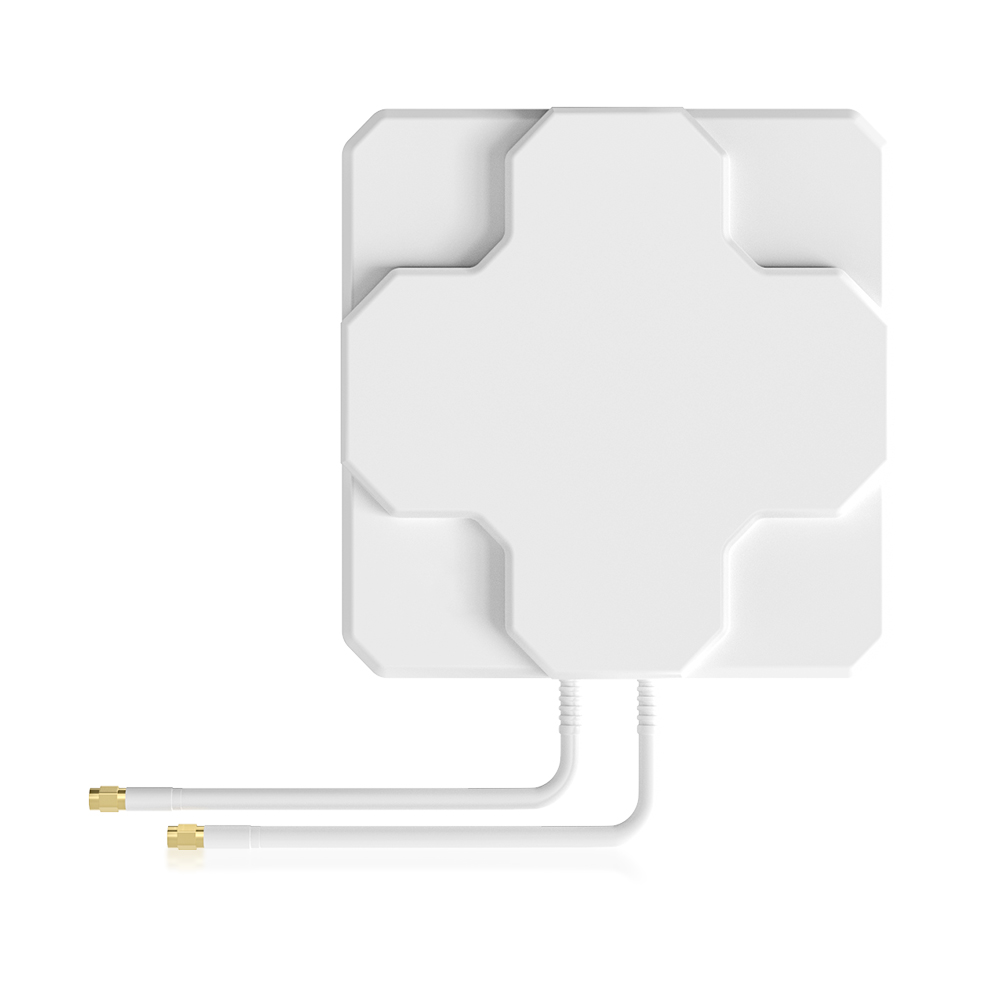
4g lte antenna,antenna 4g lte,gps 4g lte antenna,5g lte pcb antenna,3G 4G LTE 5G Antenna
Yetnorson Antenna Co., Ltd. , https://www.yetnorson.com