In the previous article, we developed several programs and explained and explained them. But the programs demonstrated are all based on the HDMI display +410c development board. If you just want to simply operate the file system on a PC, then it is very cumbersome to have a 1080p display. And most importantly, the 410c Android system can only support 1080p and lower display screens, so we naturally encounter many problems when developing. I am also unable to handle it due to the limitations of the display during the development process. Therefore, this article mainly introduces how to use the serial port to debug the development board.
UART console setting method on 410CWhen it comes to serial debugging, many embedded developers should be very familiar. But unfortunately, Qualcomm official did not recommend the UART serial port debugging method, and the official information is also very missing. But through the information on the Github wiki, I finally found the serial debugging method in a short paragraph of text, the original is as follows:
A UART serial console can be opTIonally connected from a host PC USB
Port to UART1, which is available on the DB410c low speed expansion
Connector (J8). This allows a developer to bring up a terminal
Emulator on the host PC and communicate with the DB410c using a
Command line interface. This can be very valuable when performing in
Depth debugging as well as using fastboot. The following defines the
Pins used for UART1 on the J8 connector:
• PIN1 is GND
• PIN11 is TX
• PIN13 is RX
A standard USB TTL FTDI cable, such as Part Number:
TTL-232RG-VREG1V8-WE, that steps up the 1.8 volts available on the
DB410c is required. If one with the part number highlighted is used,
The the pinout is as follows:
• BLACK -> PIN1
• YELLOW -> PIN11
• ORANGE -> PIN13
As can be seen from the above, the official PIN11, PIN11 and PIN13 on the low-speed expansion port provide a UART interface. Corresponding to PIN1: GND, PIN11: sender, PIN13: receiver
Then we can connect to the UART port through these three pins for debugging.
Required equipmentThe official offer of the UART to USB wiring purchase link, but the price is too expensive, and the cost of shipping to the country is not cheap. Therefore, we can directly purchase the UART to USB adapter cable, but be sure to note that the patch cable must support 1.8v input. If you use a 3.3/5v patch cord, the serial port information of 410c cannot be received:
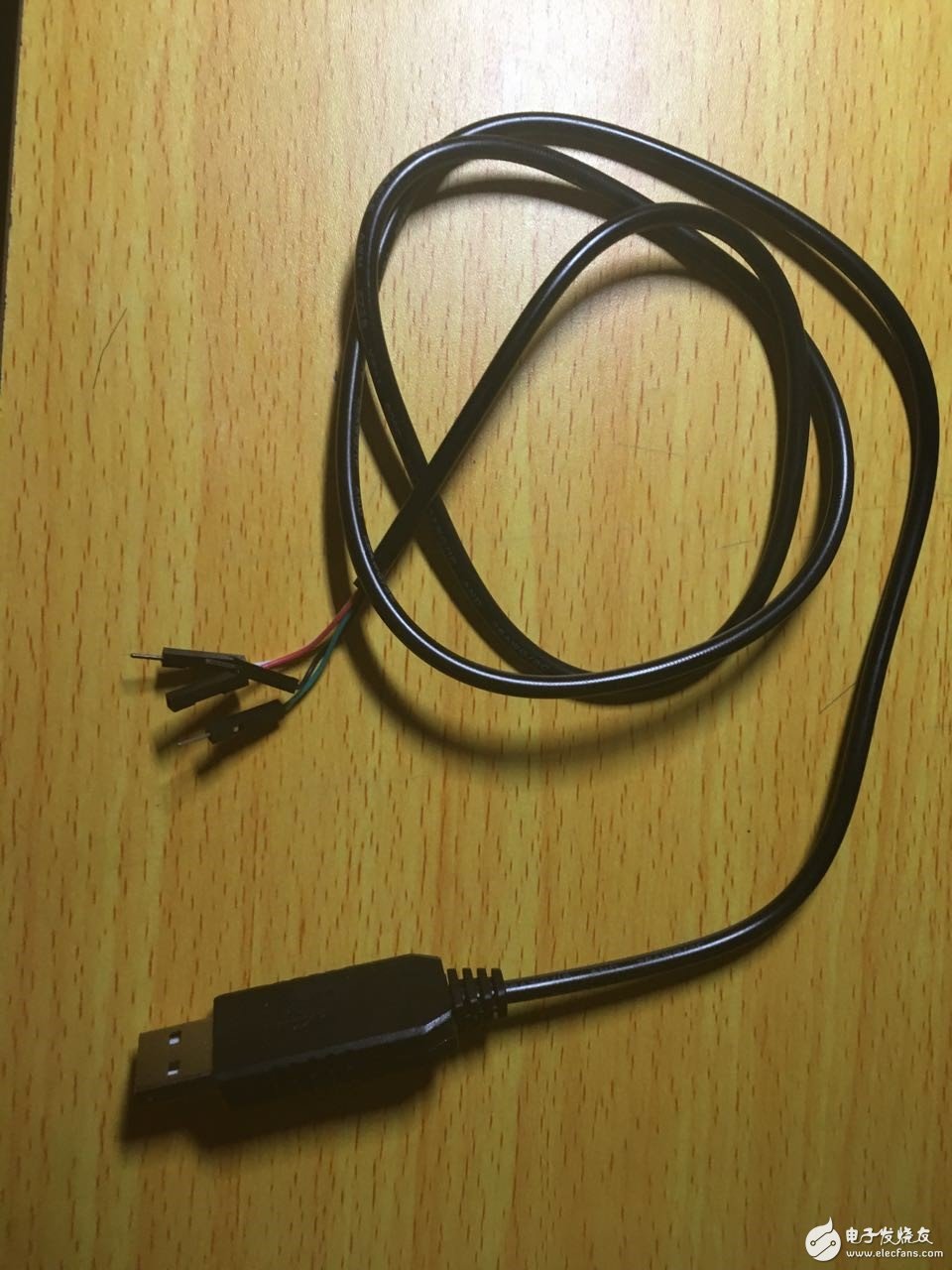
Adapter cable purchased from Taobao
If you don't know how to buy the patch cord, you can search for 1.8v UART USB directly on Taobao's official website. There are many manufacturers selling such lines now, and the price is only about 8-20 RMB.
Start connecting and configuring with 410cAccording to the explanation given by Taobao store, we need to connect the TX of the patch cord to the RX of 410c, and connect the RX of the patch cord to the TX of 410c, and also connect the black line, that is, GND to PIN1.
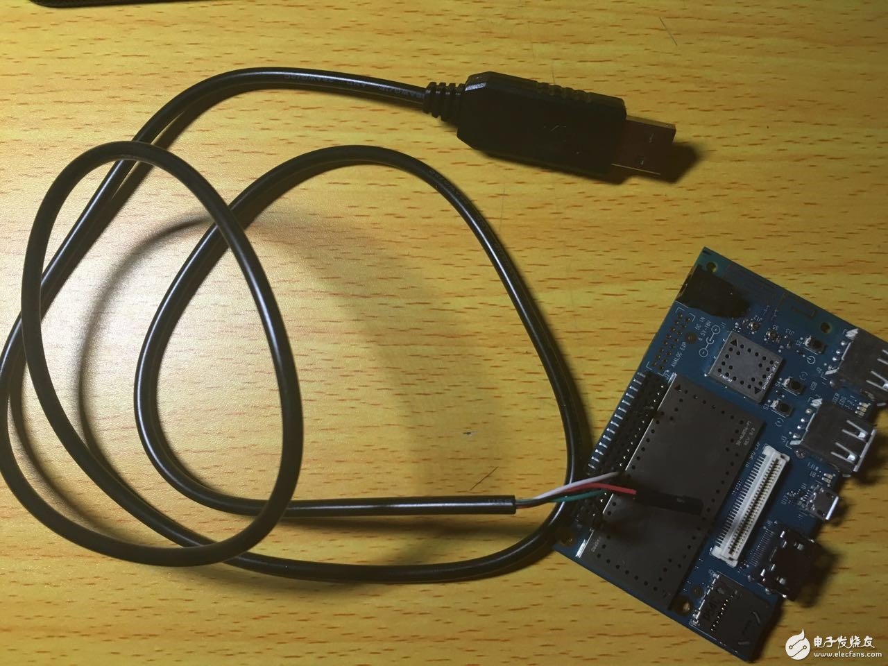
This we only need one to compare and you can connect completely. Be sure to confirm more before powering up. Do not short-circuit GND and VCC. Otherwise, your $75 can be used as cannon fodder.
Connect with a computerThe next step is to connect to the computer. First we need to install a software called putty on the computer. This software is used to communicate with the serial port of the cable. We will see the information sent by 410c to us on putty later.
Putty download link: http://
After connecting, our computer will make a crisp sound, which means that the cable has been successfully installed. Then we can see the identifier of the serial port in the device manager.
On my computer, I can see that there is a USB to serial port, the name is COM4. Then this is our connection line. Here we have to remember the COM4 identifier, because we will use this identifier to connect to 410c later on putty.
Note: Some people's computers may not have a serial to USB driver, so if you can't find this device, then you are advised to ask the customer to ask what driver to download and the name of the driver chip.
Serial port configurationNext is the configuration of the serial port. We already know the address of the serial port and the baud rate of the serial port is 115200. Then we can set it according to the following putty parameter:
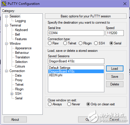
Confirmed correctly, after setting, we plug in our power supply. Then there will be countless display information on the putty side. These display information are all timely logs provided internally. It is of great significance for future debugging and testing.
to sum upIn this article, we introduced the method of connecting with the 410c using putty and the patch cord. This method works for both Android and Debian systems. In addition to buying an extra patch cord, everything else is very simple. I hope to help you develop.
Dash Cam Front And Rear,Dash Cam With Gps,Dual Channel Dashcam,2K Dash Cam Front And Rear
SHENZHEN ROSOTO TECHNOLOGY CO., LTD. , https://www.rdtkdashcam.com