The eternal topic in FPGA design during timing analysis is also the only way for FPGA developers to design advanced. Take it easy, first introduce some of the basic concepts in timing analysis.
Clock relatedThe timing characteristics of the clock are mainly divided into three points: jitter (Jitter), offset (Skew), and duty cycle distortion (Duty Cycle DistorTIon). For low-speed designs, these features are basically not considered; for high-speed designs, timing problems due to the clock itself are common, so care must be taken.
Clock jitterThe ideal clock signal should be an ideal square wave, but the edge change of the clock in reality cannot be transient. It has a low-to-high/high-to-low transition, as shown in Figure 1.
There are three common jitter parameters:
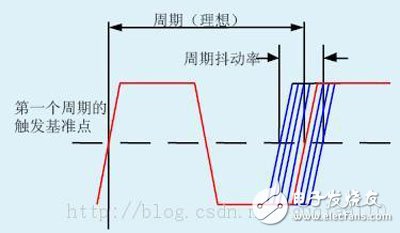
Period Jitter:
The Period Jitter measures the maximum deviation of the clock output transmission from its ideal position. The Period Jitter represents the upper and lower boundaries of the period difference jitter.
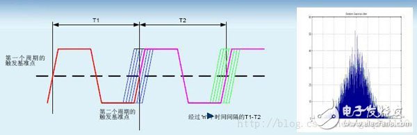
Cycle-to-cycle jitter:
The cycle-to-cycle jitter is the time offset of two adjacent cycles. It is always smaller than the period jitter (period jitter)
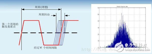
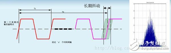
Long-term jitter (Long-term Jitter):
The long-term jitter rate is defined as a deviation from its ideal position after a delay of one clock edge relative to the reference cycle clock edge. This measurement captures the low-frequency periodic variation of the phase-locked loop (slow, low frequency). Long-term jitter is important for graphics, serial-connected communication systems, printers, and any raster scan operations.
The cause of clock jitter is noise. Clock jitter is always present, and when it is large enough to compare with the clock cycle, it affects the design, and such jitter is unacceptable.
2. Clock skewThe clock signal is supplied to the timing unit of the entire circuit, so the clock signal line is very long and constitutes a distributed RC network. Its delay is related to the length of the clock line, the load capacitance of the timing unit, and the number, so a so-called clock offset is generated. The clock offset refers to the time difference between the same clock signal reaching two different registers, and can be divided into a positive offset and a negative offset according to the difference.
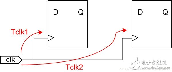
The formula for calculating the clock offset: Tskew = Tclk2 - Tclk1
The clock offset is always present, and when it is large enough, it will affect the timing of the circuit. The solution is to have the main clock signal go globally in the FPGA design. The network uses a full copper process and a tree structure, and is designed with a dedicated clock buffer and drive network. The offset to all IO cells, CLBs, and block RAM is very small and negligible.
3. Duty Cycle Distortion DCD (Duty Cycle DistorTIon)That is, the clock is asymmetrical and the pulse width of the clock changes. The DCD will devour a large amount of timing margin, causing distortion of the digital signal, causing the zero-crossing interval to deviate from the ideal position. The DCD is usually caused by the timing difference between the rising and falling edges of the signal.
2. Signal fan in / fan out (fan-in / fan-out)The number of circuits that can be fed input signals from an output device. The fanout outputs the number of circuits that can input signals from the output device.
Fan-out is a term that defines the maximum amount of digital signal input that a single logic gate can drive. Most TTL logic gates can signal 10 other digital gates or drivers. Thus, a typical TTL logic gate has 10 fanout signals.
In some digital systems, there must be a single TTL logic gate to drive more than 10 other gates or drivers. In this case, a driver called a buffer (buf) can be used between the TTL logic gate and the multiple drivers it must drive. This type of buffer has 25 to 30 fan-out signals. Logic inverters (also known as NOT gates) can assist this function in most digital circuits.
The fanout of a module refers to the number of modules directly under the module. It is generally believed that the average fanout of a well-designed system is 3 or 4. It is not ideal if the number of fanouts of a module is too large or too small, and it is more serious than too small. It is generally believed that the upper limit of fanout does not exceed 7. Fan out too large means that the management module is too complex and needs to control and coordinate too many subordinates. The solution is to increase the intermediate level appropriately. Fan-in of a module refers to how many higher-level modules call it. The larger the fan, the more the module is shared by more superior modules. This is of course what we hope for. However, it is not possible to pay for the high fan people, for example, to put together functions that are not related to each other to form a module. Although the number of fans is high, the degree of cohesion of such modules is inevitably low. This is what we should avoid.
For a well-designed system, the upper module has a higher fanout and the lower module has a higher fan. Its structure image is the tower of the mosque, with a pointed top, a wide middle, and a small bottom.
Launch edgeLaunch edge: The clock edge of the first-level register data change, which is also the starting point for static timing analysis.
4. latch edgeThe timing edge of the timing analysis: the clock edge of the data latch is also the end of the static timing analysis.
DMX Controller
MA Black Horse DMX Controller lighting console
Technical Parameter
1.Intel core 3 generation processor Inter(R) core (TM) i5-3380M CPU
2. 120 GB solid state disk, 8 GB memory, corn I5 motherboard
3.standard 6 DMX output ports and MIDI interfaces, 3072 DMX channels
4. Built-in two 19-inch high-definition touch screens
5.21 program playback putter, 42 program storage function keys
6. 1 main control dimming wheel, 4 attribute coding wheel
7. 1 mian control putter, 2 AB putter
8 Hydraulic screen Angle adjustment support structure
9.size: 82*680*130mm, G, weight: about 56KG with flycase
Our company have 13 years experience of LED Display and Stage Lights , our company mainly produce Indoor Rental LED Display, Outdoor Rental LED Display, Transparent LED Display,Indoor Fixed Indoor LED Display, Outdoor Fixed LED Display, Poster LED Display , Dance LED Display ... In additional, we also produce stage lights, such as beam lights Series, moving head lights Series, LED Par Light Series and
Controller Series,DMX Controller,Console,DMX Console
Guangzhou Chengwen Photoelectric Technology co.,ltd , https://www.cwleddisplay.com