Foreword
This article refers to the address: http://
The braking performance of a car is one of the main performances of a car. Major traffic accidents are often related to excessive braking distance and side slip during emergency braking. Therefore, the braking performance of the car is an important guarantee for safe driving of the car. At present, the ABS anti-lock braking system has been widely used in automobiles. Knowing the structure and composition of the anti-lock braking system of the car contributes to driving safety.
Structure and composition of automobile anti-lock braking system
The structural principle of the general anti-lock braking system is well known. Only the hydraulic anti-lock braking system (see Figure 1) is introduced below.
1-Brake pedal 2 - Push rod 3 - Master cylinder piston 4 - Brake master cylinder 5 - Oil pipe 6 - Brake wheel cylinder 7 - Wheel cylinder piston 8 - Brake drum 9 - Friction plate 10 - Brake shoe 11- Brake base plate 12 - support pin 13 - brake shoe return spring
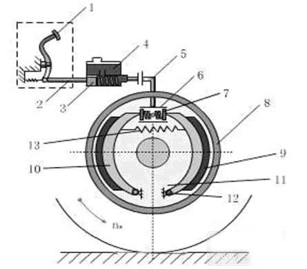
Figure 1 Structure principle of anti-lock braking system
When the vehicle is running normally, the brake shoe 10 together with the friction plate 9 maintains a certain gap between the brake drum 8 fixed on the wheel hub under the tension of the spring 13, so that the brake drum can freely rotate with the wheel. In order to decelerate or stop the running car, the driver can press the brake pedal 1 to pass the brake energy of the body through the push rod 2 and the piston 3 in the brake master cylinder 4, so as to make the system in the master cylinder. The hydrodynamic pressure flows into the brake wheel cylinder 6, and the two brake shoes 10 are pushed by the two wheel cylinder pistons 7 together with the friction plate 9 to rotate around the support pin 12, so that the outer circular surface of the friction plate is pressed against the brake drum 8 On the inner circumference.
Thus, the fixed non-rotating brake shoe friction plate applies a frictional moment Mu to the rotating brake drum in a direction opposite to the direction of rotation of the wheel. The brake drum transmits the brake braking torque to the wheel and the rear. Due to the adhesion of the wheel to the road surface, the wheel exerts a forward peripheral force on the road surface, that is, the brake braking force Fu.
At the same time, the road surface also exerts a backward reaction force on the wheel, that is, the road surface braking force Fb, which is the external force that forces the car to decelerate until braking when braking. The greater the braking force on the road, the greater the deceleration of the car. When the driver releases the brake pedal, the return spring 13 pulls the brake shoe back to the original position, and the original gap, the friction torque Mu and the braking force are restored between the outer circular surface of the friction plate and the inner circular surface of the brake drum. When Fb is released, the braking action is terminated.
In summary, it is easy to see that the road surface braking force Fb that prevents the car from traveling is not only dependent on the brake braking force Fu, but also limited by the adhesion conditions between the tire and the road surface. That is to say, the automobile brake system can obtain a large road surface braking force Fb only when it has sufficient brake braking force Fu and the road surface can provide a large adhesion force F1.
The composition of the ordinary anti-lock brake system: the ordinary service brake system usually consists of four basic parts: the energy supply device, the transmission device and the brake, but the connotation of these four basic parts changes with the development of the automobile brake technology. More abundant.
For example, the braking energy of early cars is completely powered by the driver's body, and now it has evolved to include various components for supplying, adjusting the energy required for braking and improving the state of the energy transfer medium; for example, control devices, the earliest adopting the simplest system The pedaling mechanism has now evolved to include various components that produce braking action and control braking effects; for example, transmissions, early use of mechanical linkages, now developed to include various components that transmit braking energy to the brakes; In the early stage, it was only installed on the left and right wheels of the rear axle of the car. The structure is simple and the form is single. Modern cars not only have brakes on the front axle wheels, but also have various forms and the structure is increasingly perfect and reasonable.
The main reasons why the front axle wheels of early cars were not equipped with brakes were:
1 At that time, the speed of the vehicle was low, and only the rear axle wheel was equipped with a brake to meet the requirements of driving safety.
2 Simplify the mechanical brake transmission mechanism as much as possible to improve the reliability of the transmission.
2 Prevent cars with high center of mass and short wheelbase from tipping over during braking, and improve the longitudinal stability of the car.
4 Adapt to the poor road conditions at the time, to ensure that the car still has good steering ability when braking.
Figure 2 is a schematic diagram of the double-line brake system of Liupingchai Automobile. The front wheel drum brake assembly is housed in the front wheel hub and the rear wheel drum brake assembly is mounted in the rear wheel hub. The brake pedal is mounted in front of the driver's right foot, and the hand brake control valve is mounted on the driver's right hand rear undercarriage boss (the manual valve of Jiupingchai Automobile is installed under the driver's left hand). The air compressor is mounted on the right side of the engine and is connected in series with the high-pressure fuel pump; the gas storage cylinder is mounted on the vehicle beam; the load-sensing proportional valve is mounted on the upper beam of the rear axle of the automobile, and the lower sensing transmission arm is connected to the rear axle through the spring. The brake pipe runs along the frame beam and the beam, and the pipe is connected with the brake chamber by a rubber hose.
1- front brake air chamber 2-straight-type brake valve 3-hand brake valve 4-fast release valve 5-pressure alarm switch 6-way tube 7 spring energy storage brake chamber 8-sensor storage valve 9- Rear brake light switch 10 - Air reservoir 11 - Four circuit protection valve 12 - Barometer 13 - Tee pipe joint 14 - Air compressor 15 - Gas pressure regulator 16 - Wet gas cylinder 17 - Air release valve 18 - Safety Valve 19 - Low Pressure Alarm Switch 20 - Dual Valve 21 - Four Way Connector 22 - Front Brake Light Switch
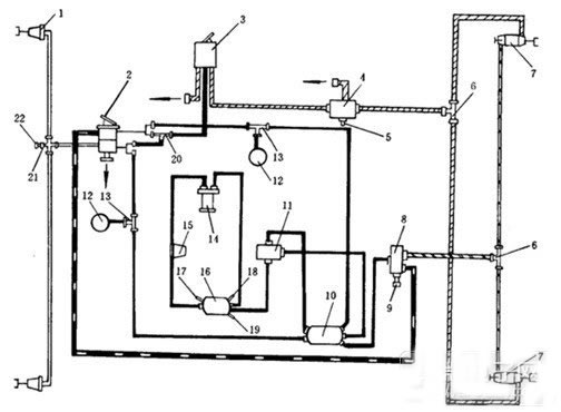
Figure 2 Liupingchai Automobile Double Pipe Brake System
Automotive brake system working process:
1 parking brake. When the vehicle is parked, the hand brake valve 3 is operated, and the compressed air in the parking brake tee 6 and the quick release valve 4 is released, so that the energy storage spring in the spring energy storage type rear brake chamber is released and pushed. The brake shoes of the rear drum brake are opened, and the friction plate is pressed against the inner circumference of the brake drum to act as a parking brake. During braking, the compressed air in the brake tee has been completely lost, and there is still parking brake.
2 Release the parking brake. The engine is started to drive the air compressor to operate, so that the brake system air supply line and the two air reservoirs are filled with compressed air, and the pressure of the compressed air can be indicated by the air pressure gauge 12. At this time, the quick release valve 4 and the air pressure alarm switch 5 connected to the parking brake air supply line have no air pressure, and the air pressure alarm switch control alarm sounds and the alarm light is on, indicating that the vehicle is in the parking brake state. When the hand brake valve 3 is operated to release the braking position, when the air pressure is low, the air pressure alarm light is still on, indicating that the brake air pressure is insufficient; when the brake air pressure is sufficient, the parking brake air supply line passes through the quick release valve 4 and the three-way The pipe joint supplies air to the parking brake air chamber, compresses the rear brake air chamber energy storage spring, returns the rear brake shoe, the rear wheel brake is in a non-braking state, and the air pressure warning light is extinguished, indicating The car has enough air pressure to start.
3 service brakes. When the air pressure of the brake system air supply line is sufficient in the driving, the pedal brake (foot brake) pedal is stepped to make the straight brake valve 2 act, and the compressed air is supplied to the front brake gas through the four-way joint 21 Room, making front wheel system
At this time, the front brake light switch 22 is turned on, and the brake light is turned on; the compressed air is proportionally supplied to the rear brake air chamber through the sensory storage valve 8 and the three-way pipe joint 6 to brake the rear wheel. The rear brake light switch 9 on the load-sensing proportional valve is turned on, and the brake light is on. The braking strength of the car is controlled by the pedal by the stepping brake valve. The pedal stroke is strong and the braking is strong; the pedal stroke is weak and the braking is weak. When the air pressure in the brake system is insufficient, the low pressure alarm switch mounted on the wet air reservoir 16 is turned on, the low pressure alarm light is on and the alarm sounds, indicating that the brake air pressure is insufficient.
4 lines of driver braking. When the brake in the vehicle is not working or there is no air pressure, the hand brake valve can be operated to the braking position to brake the rear wheel.
5 No air pressure to release the parking brake. The car is parked for a long time and may be in no air pressure. At this point the car is parked and braked. When the engine does not start, if you want to drag the car away, you can use the wrench to rotate the brake bolts of the spring brake air chambers of the two rear wheels to release the rear wheel parking brake. To resume the parking brake, turn the bolt back.
Conclusion
The ABS system is to make full use of the adhesion coefficient between the tire and the ground, so that each brake can generate as much braking force as possible without locking, and has good steering stability during braking, steering ability while braking, and shortening of braking. Advantages such as distance improve maneuverability and stability.
15.6 inch Laptop is one of the most important sizes on the market, more than 85% clients choose this size for business, teachers, middle or high school students, university students projects. 15.6 inch Gaming Laptop is ranking the first level of custom laptop, you can see i5 15.6 inch laptop, intel celeron n5095 Cheap 15.6 Inch Laptop, i7 11th 15.6 Inch Laptop In cm, etc.
15inch gaming Laptop with 11th Gen Intel Core i5-1135G7 processor ( up to 4.2GHZ, 4core, 8threads, 8MB caches) or 15.6 inch i7 1165G7 8 512gb Solid State Drive laptop ( up to 4.7GHZ, 4core, 8threads, 12MB Caches) should attractive your eyes when choose a competitive and hot gaming laptop.
Of course, other parameters levels, like 14 inch n4020 64gb laptop for online classes, 10.1 Inch Laptop equipped with 64gb rom, android 11 or windows 10 , or 11 Inch Windows Laptop in metal with 360 rotating, celeron quad core cpu, etc.
Except, 8 inch Android Tablet, Mini PC host, All In One Desktop also available here. So just share your idea about what you exactly need, then we do following for you.
15.6 Inch Laptop,15.6 Inch Gaming Laptop,15.6 Inch Laptop In Cm,I5 15.6 Inch Laptop,Cheap 15.6 Inch Laptop
Henan Shuyi Electronics Co., Ltd. , https://www.shuyiminipc.com