Center topic:
This article refers to the address: http://
HMC1055 series anisotropic magnetoresistive sensor.
The overall design of the 3D electronic compass.
Introduction to the hardware design of the 3D electronic compass system.
Interference correction for the car compass system.
solution:
Applying a transient, strong recovery magnetic field to the sensor sensing element restores or maintains sensor characteristics.
The calibration method is used to eliminate the influence of hard iron.
The triaxial design and attitude compensation allow the compass to be used in any position.
Compass is an important navigation tool that has been widely used in aircraft and marine navigation. Inertial navigation systems commonly used in aircraft and marine navigation systems are not suitable for in-vehicle use due to their high price, complex structure, and accumulated navigation errors over time. Traditional compasses, although inexpensive, cannot work in cars like cars. In an unstable environment. In addition, the traditional compass cannot be electronically output, and its signal cannot be integrated into the control system of the car, which brings inconvenience to realize intelligent transportation based on precise navigation.
In view of the above problems, this paper fully considers the instability of the internal environment of the car and the interference of the automobile engine with the magnetic field. A magneto-resistive electronic compass system is designed by using the magnetoresistive sensor.
HMC1055 series anisotropic magnetoresistive sensor
The HMC1055 series integrates the HMC1051Z single-axis magnetoresistive sensor, the HMC1052 dual-axis magnetoresistive sensor and a two-axis MEMSIC MXS3334UL accelerometer.
The HMC1052 is a dual-axis magnetoresistive sensor, each with a Wheatstone bridge made of an iron-nickel film alloy. When the bridge is energized with a supply voltage, the sensor converts the magnetic field strength into a voltage output. The HMC1052 contains two sensitive components whose sensitive axes are perpendicular to each other and whose parameters match each other. The internal circuit is shown in Figure 1.
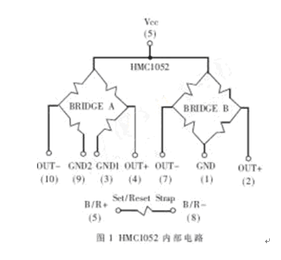
In addition to the Wheatstone bridge, the HMC1052 has two magnetic coupling strips on the chip: the bias strip and the set/reset strap. Both sensors have both straps. The set/reset band is used to ensure accuracy; the bias band is used to calibrate the sensor or to bias any unwanted magnetic fields.
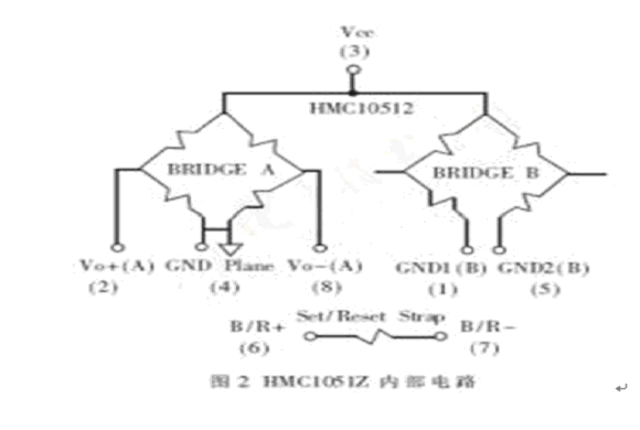
The HMC1051Z is a single-axis version of the HMC1052 with the same parameters as the HMC1052. The internal circuit of HMC10512 is shown as in Fig. 2.
The MEMSIC MXS3334UL is a two-axis accelerometer that provides a digitally represented gravitational acceleration value. When the sensor is placed horizontally, the two outputs provide a 100Hz, 50% duty cycle square wave. As the sensor tilts, its output duty cycle changes [1].
3D electronic compass overall design
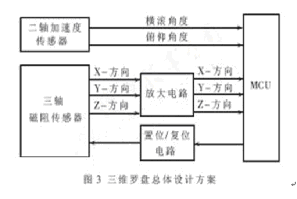
The strength of the earth's magnetic field is about 0.6 gauss. The existing magnetoresistive sensor can measure the magnetic field strength in the range of the earth's magnetic field. Since the two-dimensional compass can only work normally while maintaining the level, if it is used in a dynamic environment of the vehicle, it will not be possible to ensure that it is always level, so in this case, the usability of the compass is greatly reduced. It is then necessary to design a three-dimensional compass to accommodate measurements of various poses. The overall design of the three-dimensional electronic compass is shown in Figure 3. The three-axis magnetoresistive sensor outputs voltages from the three magnetic field strength directions of X, Y, and Z, respectively, and is input to three MCU ports with A/D conversion capability through an amplifying circuit, and the two-axis acceleration sensor measures the pitch angle and the roll angle. The meaning of the measurement parameters is shown in Figure 4.
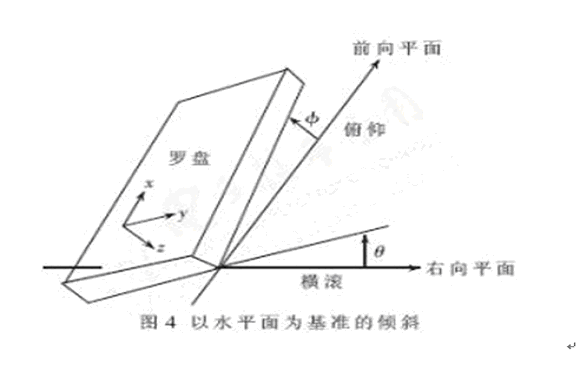
Substituting the measured X, Y, Z, θ, and Φ into equations (1) and (2):
H=Xcos(Φ)+Ysin(θ)sin(Φ)-Zcos(θ)sin(Φ)(1)
H=Ycos(θ)+Zsin(θ)(2)
Thereby obtaining the component (XH, YH) of the magnetic field strength in the horizontal plane, by the formula (3):
Azimuth Φ=arctan(YH/XH)(3)
It is possible to calculate the value of the azimuth angle Φ.
Hardware design of 3D electronic compass system
The magnetoresistive compass consists of five parts: a three-axis magnetoresistive sensor, a two-axis acceleration sensor, a signal amplifying circuit, a set/reset circuit, and an MCU system.
a design of the amplifier circuit
The anisotropic magnetoresistive (AMR) sensor operates from a Wheatstone bridge and the sensor output voltage is small and requires amplification for A/D conversion. The following takes the HMC1052 as an example for analysis. The sensitivity of the HMC1052 is ±1.0mV/V/Gauss and the bridge bias voltage is ±1mV/V. At bridge voltages of 3V and 625 milligauss maximum magnetic field strength, the bridge bias voltage is:
Vo ff = (3.0V) × (±1.0mV/V) = ±3.0mV
The maximum magnetic field swing is:
V magnetic field = (3.0V) × (±1.0mV/V/Guass) × (0.625Guass) = ± 1.875mV
Therefore, the total swing of the bridge output is:
Vout =Vo ff +V magnetic field = (±3.0mV) + (±1.875mV) = ±4.875mV
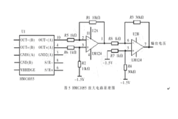
After the above analysis, a dual op amp is used to design the basic circuit, and the required voltage signal is amplified for A/D conversion. Figure 5 shows a typical scheme for an HMC1052 amplifier circuit. Since Vout = ± 4.875mV, the ADC samples are in the range of 0 to 3V or 1.5 ± 1.5V, which allows the op amp to adjust its gain to amplify the ±4.875mV signal to the ±2.5V ADC range. Therefore, the gain of the op amp is:
Gain = (±1.5V) / (±4.875mV) = 307
Here, the gain is set to 300.
b design of the set/reset circuit
When subjected to strong magnetic fields, the magnetization polarity of the sensor is destroyed and the sensor characteristics are also changed. For this destructive magnetic field, a transient strong recovery magnetic field is applied to the sensor-sensitive components to restore or maintain sensor characteristics. There is a small current band on the HMC1055 series chip that can set or reset the sensor by applying a set or reset pulse to the current band.
The set pulse and reset pulse have the same effect on the sensor. The only difference is that the sign of the sensor output changes. To set or reset, a pulse current of 3 to 4 A, 20 to 50 ns is applied to the complex position band, and the set or reset pulse width is 2 μs.
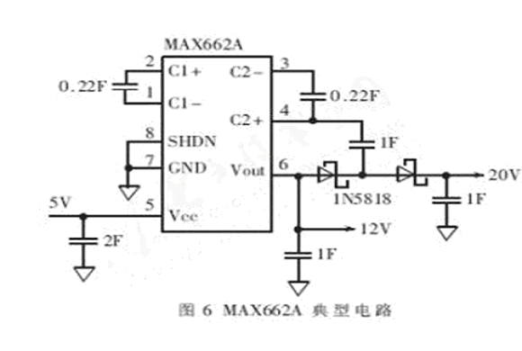
On the HMC1055 chip, the pin names of the set/reset chip are S/R+ and S/R-. There is no difference in polarity. The single set/reset has a standard resistance of 2.0Ω, so for a three-axis system, three The metal plate has a series resistance of 6.0 Ω, which produces a minimum pulse of 3 to 4 A. The supply voltage required to drive a 6 Ω load is 18 V to 24 V. Since the system chip uses a 5V power supply, it is necessary to boost the 5V voltage to about 20V, which can be done using the MAX662. A typical circuit is shown in Figure 6.
After obtaining the required voltage, the totem pole type reset circuit is designed, as shown in FIG. In the figure, SET and RESET can each be connected to one pin of the MCU, set when SET is high sensor, and reset when RESET is high.
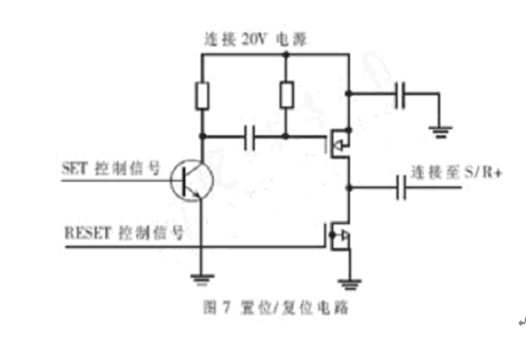
The pulse width has a direct impact on the overall power consumption, but due to the high level of interference in the car, it is recommended to be at least 2 times per second. This not only ensures the accuracy of the system, but also reduces power consumption.
System interference correction
Due to the special nature of the car's internal environment, there are many interferences around the car compass, so the interference correction problem needs to be considered when designing the car compass.
Sources of interference can be divided into Hard Iron Effects and Soft Iron Effects. Hard iron influences the changes in the magnetic field caused by permanent magnets and magnetized steel, such as in-vehicle engines, direct current, etc., which constantly imposes a magnetic field component. The influence of soft iron is generated by the geomagnetic field and is affected by the soft iron material. For example, when the car drives through a strong magnetic field, the effect is often instantaneous and weak. Therefore, when designing the vehicle compass, it is necessary to consider the influence of hard iron on the system [1].
Since the hard iron effect is constant, calibration can be used to eliminate interference. The calibration method is as follows: rotate the vehicle compass in the horizontal plane for one week, record the maximum and minimum values ​​(Xmax, Ymax), (Xmin, Ymin) in the X and Y directions, and substitute (4), (5), (6). In (7), Xo ff and Yo ff can be obtained.
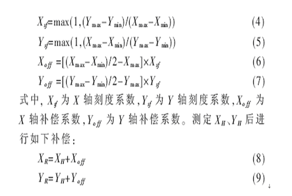
Among them, (XR, YR) is a corrected value, and they are brought into the equation (3) to obtain an azimuth angle.
The design of the electronic compass fully considers the internal instability of the car and the magnetic field interference, and adopts anti-interference technology to improve the measurement accuracy of the system. Thanks to the three-axis design and attitude compensation design, the compass can be used normally in any position. In addition, the system is digitally output via a microcontroller for integration into a GPS positioning system.
Lcd Tonch Screen For Iphone 6,Lcd Display For Iphone 6Sp,Mobile Lcd For Iphone 6Sp,Lcd Touch Screen For Iphone 6S
Shenzhen Xiangying touch photoelectric co., ltd. , https://www.starstpmobile.com