
In the first part, we focus on some ways in which noise slips into the ADC through the output and output connections. Next, look at the digital I/O lines, and finally discuss the ground connections.
The digital I/O line of the ADC is also the noise entrance. Digital I/O has many different functions, so the way noise enters the ADC is different. The most obvious is the digital output interface. More noteworthy here is the ADC with CMOS output because it uses a single-ended output.
In general, ADCs with LVDS output or serial JESD204B interface are more resistant to noise coupling. In addition to the digital output, the ADC itself has more and more digital circuits that provide some potential entry points for noise to enter through the control line. Due to the increase in digital content, I/O has to be provided for these functions. Sometimes additional I/O is done via SPI (serial port interface). Sometimes, SPI can't handle all the requirements.
Addition to SPI: SPI is not only a potential noise entry, it can also cause other conversion problems. Many people recommend not accessing the ADC's SPI while the system is running (when a conversion is taking place).
Other I/Os include mode control, shutdown, standby, overrange indicators, sync pins, and more. All of this needs to be taken seriously, in order to avoid noise coupling, in addition to a good layout, to ensure proper decoupling.
Perhaps the most overlooked entry is the grounding of the ADC. Please note that when it comes to "grounding," it means "circuit common." Also note that there are usually multiple ground connections, such as analog ground and digital ground. For both types of grounding, it is sometimes necessary to consider where they are joined or joined together.
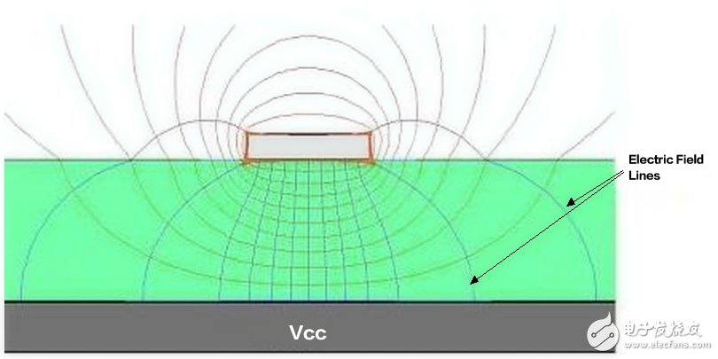
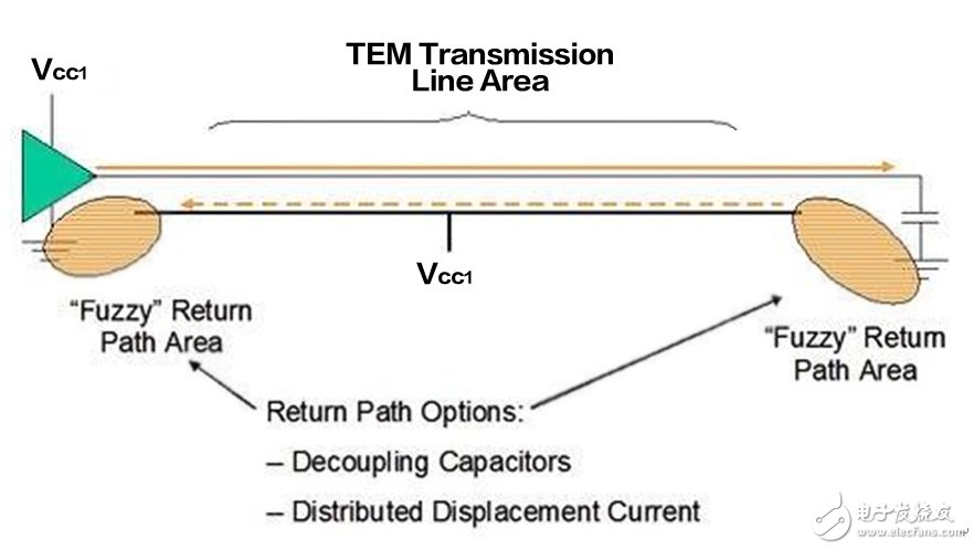
Grounding is often naturally considered a reliable reference point. However, grounding is not always a stable reference point and may allow noise to enter the ADC. It is important to pay attention to the ground plane in the system design and layout to ensure that there is sufficient flat area without cracks and sufficient ground vias to form the correct current return path. Instead of assuming that ground is a stable reference point, all current return paths in the design must be considered.
If the system is not properly designed, noise may appear at the ground plane and enter the ADC. You can get a deeper understanding of grounding, grounding current, grounding impedance, and electromagnetic fields by reading Bill Schweber's article "Understanding Your Grounding" and Bruce Archambeault's article "The Secret of Grounding." Bruce specifically discusses how the current in the trace interacts with the ground or power plane in the layer directly below the trace, and the problems caused.
The current flowing at an unexpected location is not noise in the strict sense, but it is obviously troublesome.
Now that you have all the information, you can correctly consider the noise entering the ADC's entrance. In this process, correctly understanding the different ways in which noise enters the ADC and the method of combating noise can effectively help engineers to complete excellent system design.
This article is selected from the Electronic Consumers Network June "Smart Industry Special" Change The World column, please indicate the source.
Embedded Scanners,Embedded Barcode Scanner,Embedded Qr Code Scanner,Embedded Barcode Reader
Guangzhou Winson Information Technology Co., Ltd. , https://www.barcodescanner-2d.com