The window anti-pinch function is one of the difficulties of the door control system. The door control system has a variety of fault diagnosis capabilities, which can identify short-circuit, open circuit, overheat, overload and other faults in time.
1. The overall design of the door control module
Figure 1 is a block diagram of the gate module. The microcontroller XC164CS is used to control the switching action of all power devices. At the same time, the system status is monitored regularly, and the appropriate fault feedback signal is received and implemented by the vehicle network (such as CAN bus). It exchanges fault information and button control information with the central body controller and other door controllers, so that the fault content is displayed on the user interface in time and the door is controlled in real time to ensure driving safety.

Figure 1 Overall control block diagram of the gate module
The 16-bit microcontroller XC164CS is based on the enhanced C166S V2 architecture, combining the advantages of RISC and CISC processors, and powerful computing and control capabilities through the DSP functionality of the MAC unit. The XC164CS integrates a powerful CPU core with a complete set of powerful peripheral units on a single chip, making the connection very efficient and convenient.
The electric window adopts two half-bridge intelligent power drive chips BTS7960B to form an H-bridge drive. The drive chips for the central door lock, mirror and heater are TLE6208-3G, BTS7741G and BSP752R respectively, and the driving chip of the lamp is BTS724. . These devices have provided comprehensive fault detection and protection, thus avoiding the use of excessive discrete components, greatly reducing module size and improving the EMC (electromagnetic compatibility) of the module.
The circuit of the door control module is mainly composed of the following parts: power supply circuit, electric window drive circuit, rear view mirror drive circuit, heater drive circuit, central door lock drive circuit, lamp drive circuit, CAN bus interface circuit and button interface Circuits, etc.
Hardware design of electric windows
Electric window drive circuit and starting characteristics
The window control system drives the DC motor to rotate through the intelligent power chip BTS7960. The interface circuit of the BTS7960 is shown in Figure 2. Pins 7960INH1, 7960IN1, 7960IS1, 7960INH2, 7960IN2, and 7960IS2 in the figure are connected to I/O ports P9.4, P1L.4, P5.6, P9.5, P1L.5, and P5.7 of the XC164CS, respectively.
Figure 2 BTS7960 interface connection diagram
The BTS7960 is a high current half-bridge high-integration chip for motor drive with a P-channel high-side MOSFET, an N-channel low-side MOSFET, and a driver IC. The P-channel high-side switch eliminates the need for a charge pump and thus reduces EMI. The integrated driver IC features logic level input, current diagnostics, slope regulation, dead time generation, and over temperature, over voltage, under voltage, over current, and short circuit protection. The BTS7960 on-state resistance is typically 16mΩ and the drive current is up to 43A. Therefore, even in the cold winter in the north, the safe start of the window can be guaranteed.
As shown in Figure 3, the two BTS7960s form a full bridge drive window that rises or falls. When T1 and T4 are turned on, the window rises; when T2 and T3 turn on, the window drops. The system does not have an active braking process. After the window is moved, the upper tube trigger signal stops, and the anti-parallel diode continues to flow through the lower arm of the bridge arm until the current is 0A. The freewheeling process lasts for 250ms, which is enough to meet the high power requirements of the window motor. In order to avoid the current spike at the moment of starting the window motor, the soft start function is realized by controlling the PWM signal of the frequency of 20 kHz to the lower arm switch tube.
2 BTS7960 fault detection characteristics
As shown in Figure 3, the chip inside the BTS7960 is a half bridge. The INH pin is high to enable the BTS7960. The IN pin is used to determine which MOSFET is turned on. When IN=1 and INH=1, the high-side MOSFET turns on and the OUT pin outputs a high level; when IN=0 and INH=1, the low-side MOSFET turns on and the OUT pin outputs a low level. The size of the external resistor of the SR pin can adjust the time when the MOS transistor is turned on and off, and has the function of preventing electromagnetic interference. The IS pin is the current sense output pin.

Figure 3 Schematic diagram of the full bridge drive circuit
The pin IS of the BTS7960 has a current sense function. In normal mode, the current flowing from the IS pin is proportional to the current flowing through the high-side MOS transistor. If RIS = 1kΩ, then V IS = I load / 8.5; under fault conditions, the current flowing from the IS pin is equal to I IS(lim) (about 4.5mA), the final effect is that IS is high. As shown in Figure 4, Figure (a) shows the IS pin current output in normal mode and Figure (b) shows the current output on the IS pin under fault conditions.
The experimental conditions of the BTS7960 short-circuit fault test are as follows: +12.45V battery voltage, +5V power supply, 2.0m short-circuit wire (R=0.2Ω), cross-sectional area of ​​0.75 mm, connection of 1kΩ resistor and one LED. The length between the VS and the positive electrode of the battery is 1.5 m (R = 0.15 Ω). As shown in Figure 5, where V IS is the voltage from the IS pin to ground, VL is the OUT pin to ground voltage, and IL is the short circuit current flowing through the BTS7960 when a short to ground fault occurs.
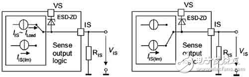
(a) (b)
Figure 4 BTS7960 current detection pin IS working principle diagram

Data Acquisition Adcs Dacs,Ics Data Acquisition Adcs/Dacs,Data Acquisition Adc / Dac Professional,Ic Chip Data Acquisition Adcs/Dacs
Shenzhen Kaixuanye Technology Co., Ltd. , https://www.iconlinekxys.com