This article refers to the address: http://
Author Email:Summary:I2C bus control is a series of binary coded pulse signals, through the program instructions to achieve microprocessor control of unit function integrated circuits and information exchange, software to replace hardware, improve control system efficiency. Thereby, the control of the television signal is realized, the CPU is the core, the memory is the memory, and the TV signal processing is performed to complete the color decoding, the image in the image, the video, the sound, the remote control, the circuit is simplified, the function is increased, and the reliability of the product is improved.
Keywords: I2C bus, pulse, E2PROM
Designing applications using the I2C bus simplifies the hardware design and makes the user “stupidâ€. In production, one and a half adjustable potentiometers can be omitted, greatly simplifying the adjustment process, achieving good product consistency and improving product reliability. Sexuality, and with fault self-test function, can shorten the inspection time and improve the inspection rate.
I. I2C control system for CD2518 color TV
The control system of color TV's I2C bus is composed of hardware circuit and software data system. The hardware circuit is composed of main control micro-processing integrated circuit, memory integrated circuit, controlled unit function integrated circuit, signal transmission circuit and power supply circuit; software A data system consists of a number of groups of binary codes with specific meanings. CD2518 color TV is mainly composed of CPU LC863328, memory AT24C08, TV signal processor LA76810, audio control CD4052 and other integrated blocks to form a control system, with CPU as the core, memory for memory, I2C bus control, to complete color decoding, image playback, view Release, sound, remote control; line and field scanning, applying digital filtering delay network, integrating all small signal processing into one chip, reducing circuit size and function. The digital automatic synchronization circuit is used to obtain a stable field frequency signal, which ensures the stability of interlaced scanning and improves the degree of automation. The use of integrated circuits to complete the functions of mid-range, video detection, AFT, etc., to simplify the circuit, to bring greater convenience to use and debugging. The memory AT24C08 assists the CPU to complete the fully automatic remote control system, enabling 255 channels to store multiple test (PAL, SECAM, B/G, D/K, NTSC, etc.) with multi-language function representation, pull-screen switch, game and Features such as calendar, automatic search, semi-automatic search, fine-tuning/manual search. The schematic diagram of its I2C bus control is as follows:
Second, the working principle of CD2518 color TV
(1) Working principle of LC863328
It is a full-format decoding integrated circuit consisting of a controller and an arithmetic unit. The controller is used to agree to direct and control the operation of the microprocessor, receive instructions one by one from the memory, decode the instructions, and issue all internal controls required for various operations at specified times through timing and control circuits. The information and the control signals required outside the CPU enable the various parts to coordinate and complete the various operations specified by the instructions. The arithmetic unit is an arithmetic/logic part ALU, an accumulator ACC, and a register, which are components for performing arithmetic operations and logical operations. It has an interrupt function, real-time control of multiple controlled devices, fetching instructions, analyzing instructions and executing instructions for programs written by people, reading control data from the memory, sending them to the controlled circuit, and using the I2C bus application software for each The indicator is adjusted to restore the image to its optimal state.
The CPU's I2C bus interface circuit is mainly composed of an address register, a shift to a bit register, a serial data register, a serial port control register, an input/output channel selector, and a filter. The shift register is connected to the data register in parallel, and is serially connected to the SDA for parallel output of parallel data serial data. Its capacity is 9 bits, and it can register an 8-bit data byte to be transmitted and 1 bit to answer ACK. The signal is generated and recognized by the I2C bus control circuit, and the data is transmitted from right to left. The SDA is allocated by the channel selection control circuit to SDA0 and SDA1. The serial port data register stores an 8bit sent by the CPU and just received. The data byte waiting for the CPU to distort the data; the data register determines the running state of the I2C bus interface according to the data, calls the corresponding operation processing program module, completes the data transfer operation of the interface; the control register provides the I2C bus input and output channel selection and response. Bit selection, serial port clock cycle selection, etc.; the address register is loaded with a 7-bit address; the input filter has an I2C bus logic compatible input level.
All controlled integrated circuits on the color TV CD2518 are connected to the LC863328 on both buses. The software pulse data transfer control information is passed. The 29-pin serial data line SDA and the 30-pin serial clock line SLC each pass a pull-up resistor RP. Connected to the positive side of the power supply, SDA, SCL must remain high when the bus is idle.
The 27-pin data data line and the 28-pin clock clock line in the LC863328 read the current instruction from the memory according to the value in the program counter PC, send it to the instruction register, and then decode the instruction operation code to decode and analyze the nature of the instruction. After the operand is fetched, the operand is operated according to the nature of the opcode, and the instruction is executed. 22, 23, 24, 25 feet control character three primary color signal output, its polarity is programmable; through the 34 feet to receive the remote control signal input, the whole machine signal parameters are adjusted. The input is controlled by 14 feet, and the retrace period is adjusted once to make the line PLL lock; the 15 feet control AGC to ensure the output video amplitude is unchanged; the field and line signals are input from 20 and 21 feet to obtain the synchronization pulse. It makes stable line and field deflection signals under different video input conditions; 40, 41, 42 feet are used to control the high frequency head band.
(B), AT24C08 structure and working principle.
The AT24C08 is an erasable and writable read-only memory that directly converts the read and write functions by changing the address code of the device in the SDA in the I2C bus. When the serial clock line SLC inputs a positive edge clock signal from pin 6, data enters each E2PROM period, and at the negative edge clock, data is output from each device; when the serial data line SDA is bidirectionally transported, the pin 5 Drive with open-drain, 1, 2, and 3 pins for device address input.
The structure of AT24C08 is mainly from the E2PROM memory array, its X, Y direction decoding circuit, power pump / timing, serial multiplexer, data register and I2C bus control logic start, end, address comparison, serial control , data load register and output, response logic circuit. The setting of the power pump is free of the write high voltage power supply except the setting; the data register guarantees the loading space of the page write data; the device address comparator is used to identify its own slave address.
The working principle is divided into four parts:
(1) Select from address
The AT24C08 is an I2C interface device with an address of 1010 in accordance with the Philips I2C interface device address assignment. In addition to the addressing byte (after SLAR/W), the on-chip memory address is addressed by an address WORDADR byte, so the on-chip addressing range is 256 bytes. The storage space of the AT24C08 is 1K bytes.
(2) page write function
When E2PROM is written, a certain write time (5~15ms) is always required. Therefore, multiple data bytes cannot be continuously written in the write program. A data register of a certain capacity is provided in the E2PROM device. When the user writes the data byte of the E2PROM at a time no more than the number of page write bytes, it can be loaded into the data register in the E2PROM at the normal RAM write speed, and then the automatic write timing control logic is started. After 5~10ms, the automatic The data in the data register is synchronously written into the specified unit of the E2PROM. The page write byte number of the AT24C08 is 16.
(3) "Rolling" of page address space
Corresponding to the number of page write bytes, the data registers have 2, 3, and 4 bit page addresses, respectively. The status part of the word address. At the time of writing, the write data is determined according to the lowest part of the word address (WORDADR) in the page address space of the data register and the lower part of the data register address. When overflow occurs, it does not carry to the upper part of the word address, which results in Write data "rolling" at the address.
(4) Data operation format
1, E2PROM write cycle timing
Due to the setting of the page write function, the I2C bus only affects the loading operation of the data register for the AT24C08. After the data is loaded, the E2PROM automatically starts an internal synchronous write cycle after receiving the stop bit sent by the I2C bus. The data in is written to the E2PROM array, and all inputs are invalid during this internal write cycle. The AT24C08 allows the bus to respond after the end of the write cycle. Write cycle timing is shown in Figure 2.
(3), the working principle of LA76810
Under the control of I2C bus, LA76810 completes the processing of image, audio IF signal, video and scan signal. After the TV IF signal is input through the 5 and 6 pins of LA76810, it is amplified by the internal image IF AGC amplifier, and the PLL phase-locked loop is demodulated. The video signal and the second audio intermediate frequency signal are generated, and the second audio intermediate frequency signal is subjected to FM demodulation, audio amplification, and volume control by the PLL circuit, and then the audio signal is output from the 1 pin of the LA76810 to the sound power amplification circuit. The video signal is output from the 46-pin and then back from the 44-pin. After the PAL, NTSC standard decoding processing, the image quality improvement processing circuit, and the R, G, and B matrix decoding circuits output the R, G, and B primary color videos from the 19, 20, and 21 pins. The signal is sent to the video amplifier for amplification, and an excitation signal is generated at the cathode of the color picture tube to complete the color image transmission function. LA76810's line and field scanning small signal generation is completed by 4MHZ clock signal frequency division and phase locking, no need to externally oscillate the crystal; after the video signal is processed by the synchronous separation circuit, the line and field synchronization signals are respectively obtained to realize the line and field scanning. Synchronization function; the generated line and field excitation pulse signals respectively scan the excitation signal from the 23-pin output field, and the 27-pin output line scans the excitation signal.
(four), CD4052 working principle
CD4052 multi-channel logic digital circuit integrated switch is used to select and mix analog signals and digital signals. After the digital signal of the control terminal is converted by logic level, it can realize small signal amplitude switching large signal amplitude function. The logic control terminal of CD4052 is 6, 9, 10 feet. When the 6 pin is low level, the common terminal is connected to other pins by controlling the potential changes of pins 9 and 10 to achieve signal gating. The purpose of the 6 feet is high, no matter how the potential of the 9 and 10 feet changes, the 13 and 3 feet are not connected to other pins.
Third, the function of CD2518 color TV
1, language function, the characters displayed on the screen can be switched between Chinese and English.
2. Calendar function, when the Chinese OSD is displayed, the lunar calendar will appear. When the English OSD is displayed, the lunar calendar will not appear.
3, the game features.
4. For lucky selection operation, select “Selection Range†or number of selection after entering the selection menu, use the volume function key to change the setting value, and the MCU randomly selects the number.
5. Select the super receiving function.
6, color automatic recognition, according to the need to choose different standards, sound and other functions.
7, select child lock, ZOOM, menu background and other functions.
8, stereo, subwoofer or headphone selection function.
Fourth, the conclusion
Using the I2C bus control system to design the color TV, the circuit board area can be reduced, the control function is increased, and the failure rate is low. The software replaces the hardware, eliminating the potential hazard of the potentiometer aging and poor contact, and improving the stability of the whole machine; Design, it is very convenient to increase or decrease the unit function circuit, which makes the product upgrade faster; multi-master control, which makes the production and maintenance debugging automatic, improves the production efficiency; the two-way transmission of data eliminates the phenomenon of out-of-control of the circuit and improves the fault judgment ability. .
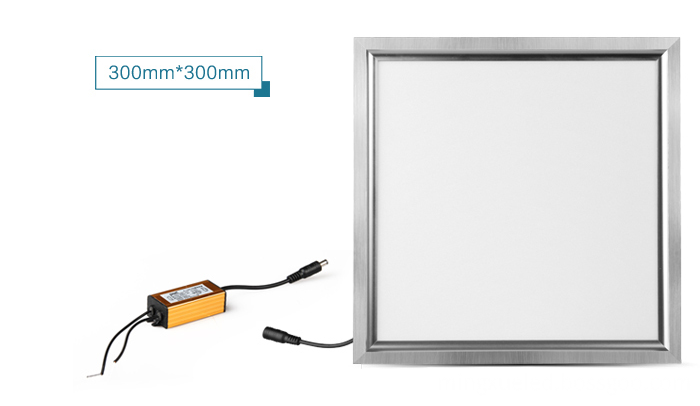
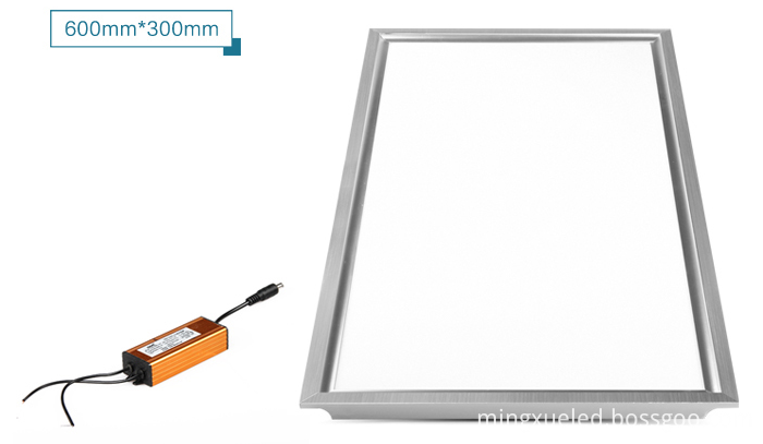
Led Panel Light is a high-end interior lighting, the outer frame made of aluminum alloy by anodic oxidation, the light source is LED, lighting design simple and beautiful, luxurious atmosphere, both good lighting effects, but also brings beautiful feeling. Unique design LED panel 18w light, the light guide plate after a high light transmittance to form a homogeneous plane glow effect, illuminance uniformity is good, light, soft, comfortable yet bright, can relieve eye fatigue. LED indoor panel lights can also radiation, will not stimulate the pregnant women, the elderly, children's skin.


LED Panel light Installation form:
1, can be mounted on the ceiling, walls and installation of surface;
2, LED Panel light may be suspended under the ceiling or mounting body. When mounted on a white ceiling, the entire ceiling was the same color, very beautiful, clean and coordinated;
3, LED panel light using broadband voltage design (AC85-240V / 50-60Hz), can be used in all countries of the world; high-power LED with isolated power, constant current or constant voltage drive, high power efficiency, power clean, stable performance ,Safe and reliable;
4, LED panel light are similar LCD TV backlight technology, a new type of surface light source, light and soft, beautiful appearance, has been widely favored by European and American businessmen, a large number of foreign investors are Buying good quality, good service, good price led Panel Light and suppliers;
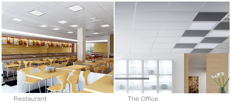
Application:

Packing with paper boxes:

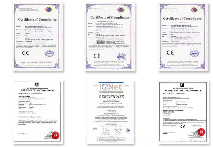
Mingxue Optoelectronics Co.,Ltd. has apply the I S O 9 0 0 1: 2 0 0 8 international quality management system certificate, for led panel light we apply the CE, RoHS and SAA certificate for our led lighting product.


Led Panel Light
Led Panel Light,Led Ceiling Panel Light,Square Led Panel Light,Outdoor Led Panel Light
Shenzhen Mingxue Optoelectronics CO.,Ltd , http://www.mingxueled.com