Abstract: Robots are widely used in dangerous and harsh environments such as military reconnaissance, mine clearance, anti-nuclear pollution, and material handling in industrial automation. As the complexity of tasks increases, the requirements for mobile robots become more and more intelligent. Turn. However, the more complete path tracking control methods are generally computationally complex and difficult to implement. It is mainly designed for the mobile robot, that is, the walking system of the smart car. The smart car with MCS-51 single chip as the control core uses the single beam reflection sampling infrared sensor to detect the obstacles in front of the front and left and right sides, and uses the control algorithm to find the traveling route. Autonomously out of the maze without control. The design adopts the wheeled moving mechanism, which enables the robot to walk straight and turn left and right, mainly for the path tracking algorithm optimization problem, and proposes an effective and feasible method. This method is simpler and easier than the previous algorithm.
This article refers to the address: http://
A robot should have several characteristics: moving functions, performing functions, feelings, and intelligence. At present, there are no more than 20 robot competitions involving hardware and software simulations held by countries all over the world. All kinds of robot games have a common purpose: to cultivate the spirit of scientific innovation, to stimulate the imagination of thinking, and to encourage the combination of theory and practice. Not only that, but now more and more automatic control products have been involved in production, and have been widely used in agriculture and industry. The new way of working will greatly shorten the time of manual work and reduce the expenditure of physical labor. The micro-machine mouse that walks through the maze is mainly based on the principle of Auto Guided Vehicle (AGV), which realizes the mouse identification route, judges and automatically avoids obstacles, and selects the correct travel route to get out of the maze. Here you choose to make a simple travel device that will allow you to avoid obstacles or labyrinths. In order to realize the car identification route, judge and automatically avoid obstacles, choose the correct travel route, the obstacle judgment uses single-beam reflection sampling infrared sensor, the drive motor adopts DC motor, and the control core adopts MCS-51 single-chip microcomputer. Control uses time-sharing multiplexing technology, and only uses one single-chip microcomputer to realize functions such as signal acquisition, line judgment, and motor control. The maze consists of 16 x 16 zones. The starting point is set at the corner and the end point is located in the center, occupying 4 areas. Each zone is 180 mm x 180 mm, with a wall height of 50 mm and a thickness of 12 mm. The sides are painted white and the bottom is painted black, as shown in Figure 1.
1 Overall design of the labyrinth control system
The maze car is composed of wall sensor, single-chip control board, power and steering system. The control block diagram is shown in Figure 2.
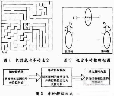
The maze car uses a wheeled movement. The advantages are: simple structure and control and mature technology. From the selected motor speed and tire diameter, the speed of the cart can be easily calculated. However, the resistance to the road surface or the driving torque of the uphill slope is an important factor. Consider this, use a plastic tire of a wireless remote control car on the tire. As shown in Fig. 3, the front wheel 1 is a universal caster or a spherical wheel, and the rear wheel 2 and the rear wheel 3 are independent drive wheels, and the steering is realized by the difference in rotational speed thereof. This combination is characterized by easy armature combination, and when the two drive wheels rotate at the same speed and in opposite directions, the car body can rotate around the midpoint of the two drive wheel wires. It is worth noting that the rotation center is inconsistent with the center of the car body. .
The choice of maze car body materials. Most of the materials used in the labyrinth are used for construction, and metal materials are generally used. The carriage and movement of the maze should not cause severe deformation and fracture, and it has sufficient strength from the mechanical point of view. The labyrinth has a small load and a light weight, and the life expectancy is not high. Therefore, use iron sheet.
1.1 Design of the control circuit of the maze car
The control circuit is mainly composed of a motor drive circuit, a single chip interface circuit, a power supply circuit and a sensor circuit. The control block diagram is shown in Figure 4.
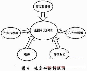
(1) Infrared light-sensing circuit sensor emits infrared light through the light-emitting diode. If an obstacle is in front, the infrared light will be reflected back and received by the photo-transistor. The single-chip program compares the signal and follows the set action request to the rear wheel. The two motors issue control commands that control the carriage to travel.
(2) The motor drive circuit uses the 89S51 single-chip microcomputer to control the action of the two drive motors through the L293D chip. According to the signal detected by the infrared sensor to the outside world, the 89S51 determines the direction of the maze vehicle according to the labyrinth path detection algorithm, and sends control commands to the left and right drive motors respectively. After the signal is driven by the L293D chip, the corresponding motor is directly controlled. The action causes the labyrinth to advance, retreat, and turn in accordance with the predetermined motion.
1.2 Maze car control program design
Control algorithm:
Maze cars generally have four control algorithms:
(1) Left algorithm
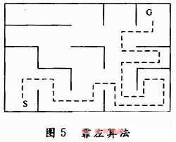
1 default to left to move. That is, you always walk along the left wall. When you have a wall on the left, you will continue along the left wall. When there is no wall on the left, turn left, and then continue to run on the left wall. This algorithm is used in the simplest maze walking method. As shown in FIG. 5, the broken line indicates the route in which the trolley advances.
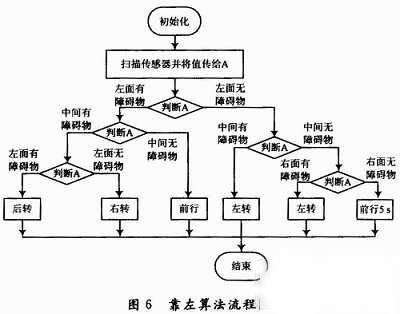
2 algorithm flow chart shown in Figure 6.
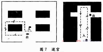
3 The disadvantages of the left algorithm. According to the algorithm, the car can walk out of the maze once in the second pass, but this road is not necessarily the shortest road; if there is an "island" in the maze itself, then the car is likely to be unable to walk out of the maze. As shown in Figure 7. The two dots in Figure 7 represent the entrance and exit respectively. The car enters the labyrinth from the entrance. Advancing to the left will cause the car to circulate in the maze all the way along the line drawn by the dotted line.
(2) Front algorithm
1 The previous algorithm is always along the road ahead (going forward without any obstacles in front), the left side is judged to the left when there is no wall, the left side is not left, and the left side is judged to the right. Then repeat the loop. This algorithm is used in the simplest maze walking method.
2 algorithm flow chart shown in Figure 8.
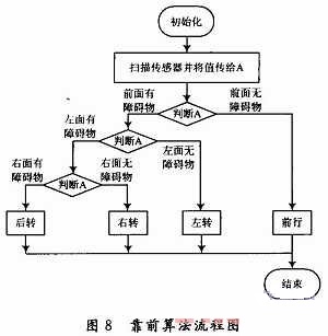
3 program idea: there is no wall in front of the front, there is a wall to judge the left side, the left side of the wall is left to turn left, the left side has a wall to judge the right side, the right side has no wall to turn right, the three sides of the wall directly back 180 °, continue Go ahead. 0 means there is a wall, 1 means no wall, p3.0 ​​means left sensor; p3.1 means front sensor; p3.2 means right sensor.
Corner control idea: Calculate the speed of the wheel, measure the distance traveled by each wheel when the car turns 90°, use the distance to remove the speed, find a time as the delay time when the car turns, and then further correct the corner by debugging.
(3) Flood algorithm
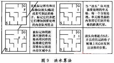
The flood algorithm uses 256 B of extra memory, which can greatly improve performance. The algorithm is 20 to 50 times more efficient than the general maze algorithm. At the same time, an area can be created in the memory, corresponding to the actual number of labyrinths. The algorithm is not too complicated in actual use. This extra memory area is called "wave" and it will be reflected in the actual state of the memory area as shown in Figure 9. When the maze is submerged, the front of a wave expands outward from the target. In the memory area, this cell is the only one that needs to be processed. When the wave reaches the starting cell grid, the robot has been flooded. In general, the starting cell can be any one of the grids. However, for the sake of convenience, the starting point is set in the first cell of the maze, and the end point is arbitrary. The reverse can also be placed in the first cell, with the starting point in the middle or desired position. Once the search is completed, the shortest path allows the machine mouse to move to the smaller grid in the surrounding grid, and the mouse can be pushed to the end.
Advantages and disadvantages of the flood algorithm:
1 According to the algorithm, when the car is going to the maze for the first time, all the roads in the maze must be walked over. But the algorithm allows the car to go through any labyrinth, even if the maze itself has an "island" car that can smoothly get out of the maze.
2 When the car goes to the labyrinth for the second time, the car can walk out of the maze once and correctly, and the route must be the shortest route.
(4) paving algorithm
Establish a region in the memory and correspond to the actual number of labyrinths, and remember all the roads that have passed. If you find a dead end or a road that has passed, you will return to the previous ramp; By default, the crossing is to the left. Because of the memory function, you can go the second time.
Advantages and disadvantages of paving algorithms:
1 Using this algorithm can go through a complicated maze, there is no problem that cannot be achieved.
2 Using this algorithm, you can walk out of the maze once in the second time when the car goes to the labyrinth, but you can't guarantee that the road is the shortest route.
These algorithms have their own advantages and disadvantages. After weighing and comparing, the algorithm is finally selected.
1.3 System operation and debugging
Problems encountered during the running of the program and solutions:
(1) The outer casing and wheels of the trolley are hand-installed, the precision is not very high, and the trolley can't always go straight during the driving process. It is easy to cause the wall accident to affect the trolley to go through the maze. If it is caused by hand-made, it can be solved by adding some tape to the backward wheels to increase the circumference of the wheel. It is also possible to improve the program by adding an A/D converter to the circuit, continuously measuring the distance between the car and the surrounding wall, and keeping the car at a certain distance from the surrounding wall.
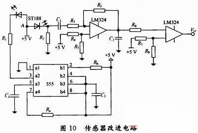
(2) Using ST188 type infrared sensor, it is not easy to be detected by external interference, and it can not detect the wall signal accurately. Especially under strong light, it can't operate normally. The light reflected by some materials can't be received, it is easy to be disturbed by sunlight, and the car can't be mistaken. Go out of the maze. The cause of the interference is that the infrared rays emitted by the sunlight are the same as the infrared rays emitted by the infrared sensor. They are continuous and cannot be distinguished, so they are susceptible to interference from ambient light. The solution to this problem is to use the basic principle of wireless remote control to make the infrared emitted by the infrared sensor a signal with a fixed frequency different from the surrounding infrared. The receiver also performs circuit processing so that the discriminating ability directly receives the infrared signal having a fixed frequency. Both improvements are achieved by improving the circuit. If it is caused by the reflecting surface, it can be solved by limiting the material of the reflecting surface. According to the 555 timer principle, the improved sensor circuit is shown in Figure 10. The working principle is that the 555 circuit emits a square wave with a frequency of 100 Hz, and drives the ST188 radiation-emitting diode to flash at a frequency of 100 Hz to emit a flickering light wave. When an obstacle approaches, the reflected light causes the photoresistor at the receiving end of the ST188 to The same frequency change causes the voltage value VA at point A in Fig. 10 to change accordingly. The VA contains a DC component V straight and an AC component V change with a frequency of 100 Hz, the latter reflecting the proximity of the obstacle. In order to preserve the useful AC signal V, the DC component V is cleared straight, and the DC blocking function is used to complete the function of the DC pass, and the V-intersection is amplified by the first op amp circuit, and realized by the second op amp. DC to AC conversion. Specifically, when away from obstacles, the output VO of the op amp is high; when the sensor approaches the obstacle, VO outputs a low level.
(3) The speed of the trolley is difficult to control. It is difficult to grasp the rotation time of the trolley through the program control. When the car rotates 90° and 180°, it often turns to the specified angle, so that the trolley cannot go straight out of the maze. One solution is to access the voltage regulating circuit. When the turning time of the car is fixed, the voltage on the motor is adjusted to change the wheel speed, and the practice is continued until the predetermined standard is reached. Another solution is to change the corner of the car by changing the corner time of the car in the case of a certain speed of the car, and practice it several times in order to achieve the intended goal. Through actual debugging, it is difficult to achieve the intended goal by using these two methods alone. Therefore, combining the two, through debugging, is easy to achieve the goal.
2 Conclusion
The robot maze car is a frequently selected project for college students' electronic production. It is a comprehensive application of electronic circuit, mechanical transmission and automatic control. The steering control of the car involves the motor speed regulation. The control model can be established for the car first, and then the specific control algorithm is given by applying the knowledge of the automatic control principle, so that the steering control and path selection of the car can be more accurate.
Camshaft And Gear Train,Iron Black End Ring,Wheel Spindle Rail,Axletree Steel Pad
Jinan Guohua Green Power Equipment Co.,Ltd. , https://www.guohuagenerator.com