In the 1990s, ultra-wideband technology has been applied in the military field. With the development of short-distance wireless communication, in 2002, the Federal Communications Commission allocated the frequency band from 3.1 to 10.6 GHz for commercial ultra-wideband communication systems. Since then, uWB technology has entered a period of rapid development.
Because the frequency range of ultra-wideband overlaps with the frequency of existing wireless communication systems, such as: WIMAX (3.4~3.6GHz), WIAN (2.4~2.484 GHz, 5.15~5.35GHz, 5.725~5.825 GHz), HIPERLAN/2 (5.15) ~5.35 GHz, 5.47~5.725 GHz) etc. In order to avoid the mutual interference of other frequency bands in the ultra-wideband communication system, the ultra-wideband antenna with notch characteristics has been extensively designed and researched.
In recent years, antenna engineers have begun to directly etch the resonant structure on or around the radiation patch of the ultra-wideband antenna, so that the antenna has notch characteristics in the interference frequency band. Commonly used notch structures are "C" or "U"-shaped slits or metal strips. However, many designs are not only complex in structure, but also mostly have single-notch characteristics.
This paper proposes a microstrip-fed ultra-wideband antenna with dual-notch characteristics. By etching two cone-shaped slits on the cone-shaped radiation patch, the antenna can obtain notch characteristics at 3.5 GHz and 5.5 GHz. The test results show that the impedance bandwidth of the antenna voltage standing wave ratio less than 2 is 2.56~10.61 GHz, and it has good double notch and omnidirectional radiation characteristics in the band.
1 The design and structure of the antennaFigure 1 shows the structure of a dual-notch ultra-wideband printed antenna with a tapered slot. The antenna is etched on a FR4 dielectric substrate with a relative dielectric constant εr of 4.4 and a thickness H of 1.52 mm. The overall size is 35 mm×30 mm, and the floor size is 30 mm×13.5 mm. The feeding part is a 50 Ω microstrip line, which has a width of 2 mm and is connected to an SMA type coaxial connector. The front of the antenna is a tapered radiating patch. Choose an appropriate size to get the ultra-wideband performance of the antenna. By introducing the upper and lower tapered slots on the radiating patch, the antenna can achieve dual notch characteristics at 3.5 GHz and 5.5 GHz.
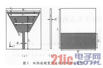
In order to analyze the influence of the improved structure on the electrical performance of the antenna, 3D electromagnetic simulation software Ansoft HFSS V13 was used to simulate and optimize the designed antenna. The antenna size determined after simulation experiment and processing and debugging is as follows: L=35 mm, L1=15 mm, L2=6.5 mm, L3=5.5 mm, L4=1.5 mm, L5=13.5 mm, W=30 mm, W1= 2 mm, W2=4 mm, W3= 29 mm, S1=2 mm, S2=1.5 mm, H=1.52 mm. The lengths of the upper and lower gaps are respectively p1=25 mm and p2=16 mm.
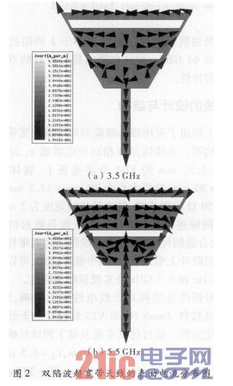
2 Result analysisFigure 2 shows the simulated surface current distribution of the antenna at frequencies of 3.5 GHz and 5.5 GHz. It can be seen that when the antenna is working at 3.5 GHz, the surface current is mainly concentrated around the upper cone-shaped slit; when the antenna is working at 5.5 GHz, the surface current is mainly concentrated around the lower cone-shaped slit. At this time, the current directions on the upper and lower sides of the slot are opposite, and the antenna works in a quasi-transmission line mode. Since the length of the slot is about 1/4 wavelength, this mode transforms the high impedance on the upper side of the slot into zero impedance on the lower side, resulting in impedance mismatch of the antenna, causing the antenna to be unable to radiate outwards, thus forming the antenna trap Sex.
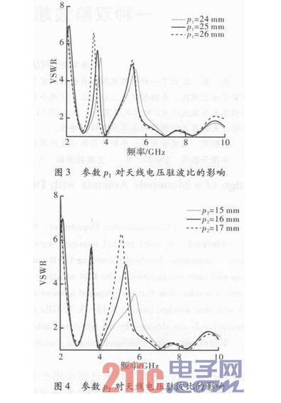
Figures 3 and 4 respectively show the simulation results of the antenna voltage standing wave ratio when the slot lengths p1 and p2 take different values. As shown in the figure, it can be seen that adjusting the length of the tapered slot can change the position of the notch frequency band, and basically does not affect other working frequency bands.
A vector network analyzer Agilent-E5071B was used to test the processed antenna model. Figure 5 shows the simulation and measured results of the antenna voltage standing wave ratio with or without a tapered slot. It can be seen that the measured curve of the antenna voltage standing wave ratio is basically consistent with the simulation results, and the difference in the frequency band may be caused by processing errors and the measurement environment. After introducing the tapered slot, the antenna obviously produces two notch frequency bands (3.18~3.76 GHz and 4.4~5.75 GHz). The actual measurement results show that the working frequency band of the antenna model's voltage standing wave ratio ≦2 is 2.56~10.61 GHz, which meets the basic requirements of the UWB communication system for working bandwidth.
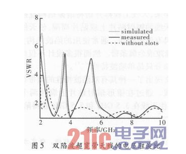
Figure 6 shows the measured far-field pattern at frequencies of 3.1 GHz, 4 GHz, and 8 GHz, respectively. In the y-z plane (E plane), the antenna radiation pattern has a pattern similar to that of a monopole antenna; in the zy plane (H plane), the antenna radiation pattern is approximately omnidirectional.
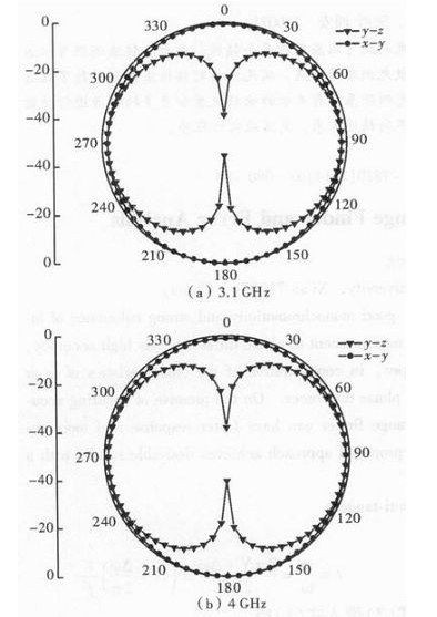
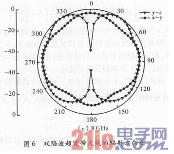
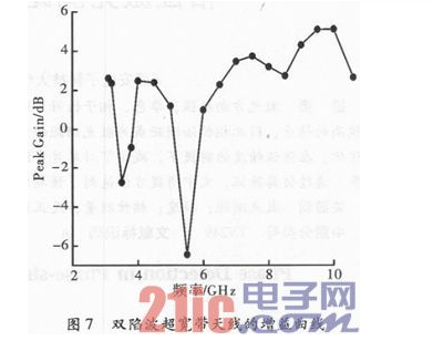
Figure 7 shows the measured gain curve of the antenna in the working frequency band. As shown in the figure, the antenna gain drops significantly in the 3.5 GHz and 5.5 GHz frequency bands, indicating that the antenna has good double notch characteristics.
This paper presents a new type of dual-notch ultra-wideband printed monopole antenna for UWB communication system. Utilizing the improved cone-shaped radiation patch and the cone-shaped slot, the antenna forms an ultra-wideband antenna with double notch characteristics. The actual measurement results show that the antenna satisfies the impedance bandwidth of UWB communication, and has good double notch characteristics and omnidirectional radiation characteristics. Therefore, the antenna has better application prospects in wireless hyperband communication systems.
Shenzhen E-wisdom Network Technology Co., Ltd. , https://www.healthy-cigarettes.com