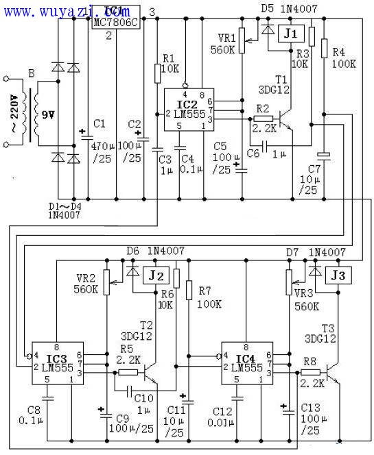
First, the working principle of the circuit
In the circuit, three monolithic integrated circuits are composed of three time base integrated circuits LM555, and each monostable circuit is used as a timing control unit. The three units work together to complete the three-stage loop timing control function. At the moment of power-on, since the reset terminals 4 of the 555 integrated circuits IC3 and IC4 are connected with automatic reset circuits with large time constants (composed of R4, C7, and R7, C11, respectively), IC3 and IC4 are reset. The output terminal 3 outputs a low level, so that the transistors T2 and T3 are respectively turned off, and the relays J2 and J3 are released. Since the IC2 reset terminal 4 pin is directly connected to the positive pole of the power supply, the voltage on the capacitor C3 cannot be abrupt when the power is turned on. The trigger pin of the IC2 trigger terminal 2 is triggered to make it enter the transient state. The 3-pin output is high level, and the triode T1 Turn on, relay J1 pulls in, J1 contact can control the electric appliance to work. At the same time, the power supply is charged to the capacitor C5 via the potentiometer VR1. When the voltage on the C5 rises to two-thirds (4V) of the power supply voltage, the IC2 ends the temporary stabilization, and the 3-pin output low level turns off the transistor T1, the relay J1 Release, the electrical device whose contact control is powered off stops working. Adjusting the parameters of potentiometer VR1 and capacitor C5 can change the pull-in time of relay J1. At the instant when IC2 outputs a low potential, the differential circuit consisting of capacitor C6 and resistor R3 will generate a negative spike at the trigger pin 2 of IC3, triggering IC3 to enter the transient state, and its output terminal 3 outputs a high potential, making the transistor T2 is turned on, relay J2 is pulled in, and the electrical device controlled by the contact is energized. Adjusting the parameters of potentiometer VR2 and capacitor C9 can change the transient time.

When the second unit is temporarily terminated, the differential circuit consisting of capacitor C10 and resistor R6 will generate a negative spike at the trigger terminal 2 of IC4, triggering IC4 to enter the transient state, and its output terminal 3 outputs a high potential. The transistor T3 is turned on, the relay J3 is pulled in, and the electrical device controlled by the contacts is energized. Adjusting the parameters of potentiometer VR3 and capacitor C13 can change the transient time. When the third unit is temporarily terminated, the first unit circuit is triggered by the differentiating circuits C3 and R1, so that the loop timing control is implemented in sequence.
Angled Finish Nail,Resists Moisture Nail,Hardware Angled Finish Staple,Reliable 0.087 Inch Nail
Zhejiang Best Nail Industrial Co., Ltd. , https://www.beststaple.com