When driving a direct-sampling high-speed ADC, the most likely place to degrade performance is the interface between the final amplifier and the ADC.
Any direct sampling ADC produces a nonlinear charge during the sampling process. This charge is reflected into the input network each time the sampling switch is closed. If not attenuated, it is reflected back to the ADC and resampled, causing the ADC's distortion or intermodulation distortion performance to degrade. The input network of the ADC should be as close as possible to 50 Ω to maximize this nonlinear charge. The use of a highly absorptive filter suppresses the nonlinear tones produced during the sampling process, thereby improving SFDR.
Driving the ADC AD9265 with the LTC6409 amplifier

The LTC6409 is a differential amplifier with excellent linearity and is ideal for driving the AD9265.
The AD9265 is a 16-bit 125Msps high performance ADC with SNR better than 77dB at 100MHz and SFDR better than 89dB.
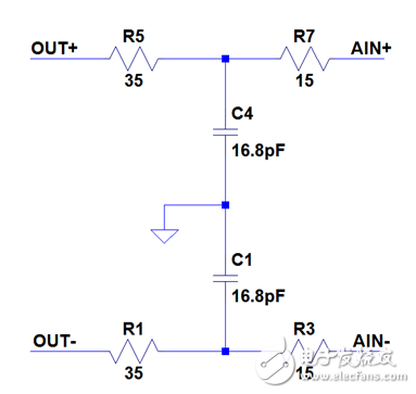
When designing the input network, if you choose improperly, the above features may not be guaranteed quickly. In almost all cases, a filter is required between the ADC and the amplifier to reduce the broadband noise of the final filter. The design and layout of this filter is critical. It should be an absorption type that absorbs high frequency nonlinear components from the sampling process into a 50Ω termination resistor without allowing it to be reflected back to the ADC input.
Figure 1 shows an absorption filter network that can be used between the LTC6409 and the AD9265.
Figure 1: Filter network between the LTC6409 and the AD9265 |
Figure 2 shows the filter response performance. This filter does not need to have high selectivity, its function is only to attenuate the broadband noise of the amplifier and the nonlinear components in the sampling process. At high frequencies, the inductor is open and the capacitor is shorted, and the high frequency component of the sampling process is introduced into the 50Ω termination resistor. If the trace is placed at a 50Ω resistor, there will be no loop reflection and the SFDR of the ADC will not drop.
Figure 2: Simulated filter response of the circuit shown in Figure 1. |
Another possible cause of distortion is the asymmetrical input network layout. In an ideal layout, the differential nature of the signal provides excellent common mode rejection and very low second harmonic distortion. Any symmetry deviation will cause a mismatch in the differential signal, which is manifested as second harmonic distortion. Even a very simple design decision, such as copper filling closer to one side of the differential signal, can cause ground current differences in adjacent ground planes. This will increase system distortion. For best performance, absolute symmetry must be maintained.
Figure 3 shows the PCB layout of the LTC6409 driving the AD9265 and the filter network. Measures have been taken to protect the symmetry of the network and to properly position the absorbing components to optimize their performance. The position of the first set of absorbing elements allows it to absorb any high frequency products immediately. The main signal path is wound around the grounded copper foil until it reaches the second set of absorbing elements, eventually reaching the source termination resistor at the amplifier side. This network maximizes the performance of the LTC6409 and AD9265.
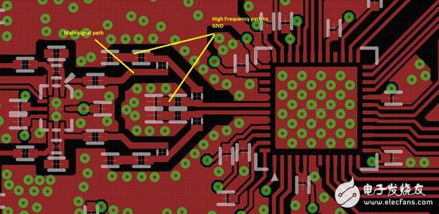
Figure 3: Layout of the LTC6409 and AD9265
To compare the performance of the LTC6409 and AD9265, a board was designed to connect the PScope software via the DC890. The absorption filter of Figure 1 and the reflection filter of Figure 4 were filled and tested at different frequencies.
Figure 4: Reflective filter used between the LTC6409 and the AD9265 |
The AD9265 uses a 125Msps low jitter clock, and the LTC6409 is driven with a filtered sinusoidal signal from 48.1 to 178.1 MHz. SNR and SFDR are recorded using PScope. The collected sample data can be seen in Figure 5.
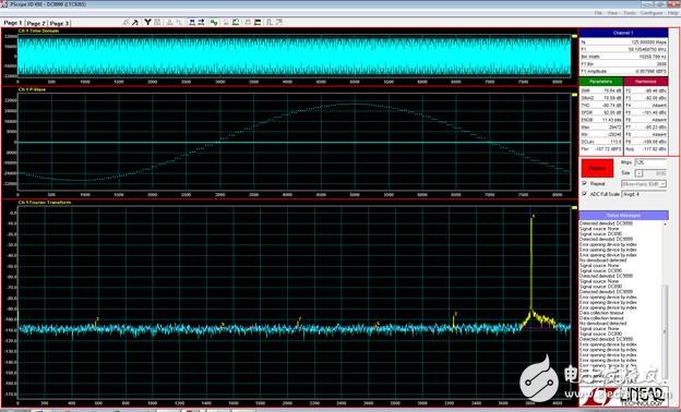
Figure 5: Sample data collected by PScope samples 58.1 MHz at 125 Msps
The SNR and SFDR comparisons using an absorption filter and a reflection filter are shown in Figures 6 and 7.
SFDR with absorption network is better from beginning to end, exceeding 10dB at some points;
The SNR is also better from start to finish, and at very high frequencies, the SNR is determined by other factors.
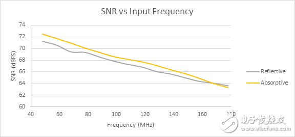
Figure 6: SNR comparison of absorption and reflection filters
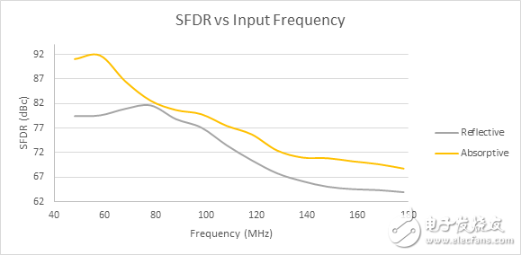
Figure 7: SFDR comparison of absorption and reflection filters
Systems with absorbing networks perform better than systems that use reflective networks. When using a reflective network, the outstanding performance of the LTC6409 and AD9265 will degrade. The results are clear for the LTC6409 and AD9265, but the use of a highly absorptive and symmetrical input network can also be applied to any direct sampling ADC and differential amplifier. The highest performance is achieved by working with the interface between the amplifier and the ADC.
LED DJ Console Display is a kind of led electronic display screen designed and made according to the customer's specific requirements. DJ Table LED Display Stage can be applied in many fields due to its flexibility of control and combination. It is a bar mark, which is the most distinctive stage facade.
It has an impact on the stage, starts from this moment. It can be widely used in bars, KTV, stage performance and other places.
Characteristics
1. Exquisite effect, smooth transition
2. Assemble and disassemble design, quick and convenient maintenance
3. Innovative unique creation, bar vision 3D design concept
LED DJ Console Display, Fantasy LED DJ Console Display, Video LED DJ Console Display, LED Honeycomb DJ Console Display
Shenzhen Priva Tech Co., Ltd. , https://www.privaled.com


