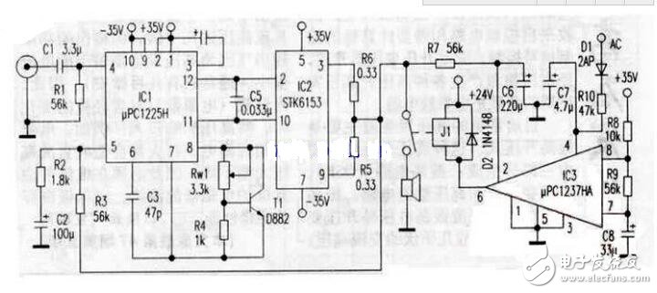
The internal pre-stage of STK6153 adopts a constant voltage source bias, which can better stabilize the working state of the output stage, but the constant voltage bias between the STK6153 ④ pin and the ①pin can only provide a quiescent current of about 10mA. To a certain extent, this caused severe crossover distortion and tight treble in the amplifier. In addition, the final current output area of ​​the STK6153 chip is much larger than the LM1875, TDA1514 and other sets, so the internal resistance is smaller and the power margin is larger. However, the STK6153 open-collector output form increases the output impedance of the amplifier, making the above advantages unavailable. In response to the above-mentioned defects, I gave up the STK6153's pre-stage bias and changed the rear stage to the emitter output. At the same time, uPC1225H was used to promote STK6153 for current amplification to produce a high-quality low-cost Hi-Fi amplifier.
uPC1225H is a 50W audio drive circuit launched by NEC. The chip is equipped with a complete protection link. Although the peripheral circuit is slightly more complicated, the output voltage deviation of uPC1225H is only ± 5mV. The extremely wide power frequency band and the high conversion rate make it It is warmer, softer and more audible than the successful sounds of LM3886 and other collections.
The acceleration capacitor C5 in the circuit diagram has a significant effect on the high-frequency output of the power amplifier. The capacity should not be too large. It is best to use CBB capacitors. T1 can choose any low frequency medium power NPN tube. Rw1 is the only component in the circuit that needs to be adjusted. By adjusting Rw1 to change the voltage between the c and e poles of transistor T1, the bias voltage of the final output tube of the power amplifier can be finely adjusted. Under amateur conditions, the circuit is installed and the dummy load is connected after the inspection is correct. In the static state, carefully adjust Rw1 with a screwdriver to minimize the output potential of the midpoint to ground. The temperature rise of uPC1225H and STK6153 are relatively high, and a suitable heat sink should be added.
The system also designed a group of speaker protection circuits composed of uPC1237HA. D1 selects a germanium diode, its anode is connected to any AC output terminal of the transformer secondary, and the relay J1 is directly powered by the 24V voltage provided by the LM7824.
Practice has proved that the combination of STK6153 and uPC1225H takes into account the advantages of both. Not only does it retain good low-frequency strength and F-deep depth, but the flexibility and high-frequency resolution of the power amplifier are more obvious than those made with STK6153 + STK3048A improve.

STK3048 and STK6153 are thick-film power amplifier integrated circuits from Sanyo Corporation of Japan. STK3048 is a pre-amplifier integrated circuit; STK6153 is a post-amplifier integrated circuit.
STK3048 is a 15-pin dual-channel single-row thick film package. Its exposed heat sink is connected to pin (8), but it is insulated from the internal circuit. (8) After the foot is grounded, it has a certain shielding effect on the internal circuit. There is no need to install a radiator when the thick film block is working.
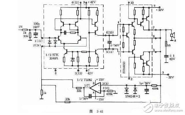
There are two stages inside STK3048. The input stage has a differential amplifier with protection. The two diodes at the base of the differential tube protect. Its collector-capacitor series phase compensation network can prevent the input stage from generating transient distortion due to the burst signal. A set of mirror current sources is connected between the two collectors. The purpose of this circuit to connect people is to invert the current of the right input tube linearly and the left input tube to form two subtractive current sources, and implement current excitation to the subsequent stage. The main voltage amplifier stage is a common base common emitter circuit. The upper tube performs broadband amplification of the signal and provides impedance matching for the direct coupling between the input and output stages; the lower tube linearly outputs the amplified current of the upper tube to reduce the opening of the stage The ring is distorted and provides greater excitation power to the subsequent stage. The two-stage amplifier tube is supplemented by a constant current source as a load, which has strong suppression of power supply ripple.
STK6153 is a 10-pin mono channel single-row thick film package (two channels are required for two channels). The internal circuit has been electrically insulated from the exposed heat sink. STK6153 internally integrates constant voltage source bias, non-pre-stage push and non-stage composite current amplifier circuit. Adopting a fully complementary symmetrical structure, it has excellent characteristics such as high speed, high precision, high power and low noise. Due to the built-in bias of the constant voltage source, the unstaged high-power tube is always in the best working state and has excellent temperature compensation. The complementary output of the thick film block is designed as an inverted Darlington compound circuit, which outputs in the form of an open collector, which can reduce the output impedance.
The power amplifier circuit composed of STK3048 and STK6153 is shown in Figure 3-41 (the power supply and protection circuit are omitted). The internal circuits of the front and rear ICs are respectively analyzed in the dotted frame. The pre-stage small capacitors can use German-made WIMA or ERO high-quality capacitors, and the large electrolytic used for power supply filtering uses Nissan Marcon NIPPON, CHEMICON Nitsuko, Rubycon brand capacitors as the best. Each large electrolytic is connected in parallel with a WIMA 0.1uF ~ 0.33uF small Capacitor to improve frequency characteristics. The circuit can work normally without debugging. In terms of overall listening experience, the frequency bands in the full range are very balanced, with large dynamics, wide frequency response, low distortion, fast transient response, pure and powerful sound quality, and particularly low noise. Circuit sinusoidal power; 2X100W, distortion.

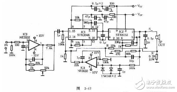
The internal circuit of STK3048 and STK6153 is relatively simple, and its sound quality is very good. However, the design of the peripheral circuit and the selection of peripheral components have a great influence on the sound quality of the IC, so this power amplifier uses the circuit shown in Figure 3-42.

1. Use Gm to control the volume, enter the volume potentiometer and connect it to the gain control point of IC3 (NE5532), and change its negative feedback depth to change the volume. STK3048 works in the best stable state. There is almost no sliding noise when adjusting the volume. More importantly, the dynamic range remains the same when playing at a low volume, and the music details are vividly displayed at a large volume, without any sense of drag.
2. Adopt constant current negative feedback circuit, linear resistance R and R 'variable amplifier constant voltage mode is constant current mode to drive the load, so that the transient characteristics of the power amplifier can be improved, enhance the strength of bass and the clarity of treble.
3. Cancel the loop negative feedback capacitor, IC4 (NE5532) and peripheral components constitute the output midpoint zero servo circuit. Used to servo the â‘¡ and (14) pins of STK3048, the DC potential of the output end of STK6153 drifts after the feedback capacitor is cancelled, and the high and low frequency resolution of the amplifier is improved.
The amplifier's subjective listening evaluation: the treble is slender and clear, the midrange is bright and clear, the bass is full and strong, the sound range is clear, the harmonic distortion is small, the noise is low, and the dynamic range is extremely wide. Due to the large output power of this circuit, it should be noted that the power supply used must have sufficient capacity, and the STK6153 radiator should not be too small. The op amp IC is powered by an independent active servo power supply. In addition, the amplifier must be equipped with a speaker protection circuit
The categories of Modular UPS Power Supply are described as follows:
I. Definition and overview
Modular UPS power supply is a design architecture that divides the UPS system into multiple independent modules. Each module contains complete power conversion functions, such as inverters, rectifiers, batteries and control circuits, and can be operated independently, and modules can be added or reduced according to demand to adapt to different load requirements. This design improves the flexibility, reliability and maintainability of the UPS system.
Second, the main composition
Modular UPS power supply usually consists of the following main components:
Rack: The infrastructure that supports and holds each module.
UPS power module: Contains core power conversion components such as inverters, rectifiers, and chargers, which are responsible for converting input mains or battery power into stable AC power output.
Static switching module: Switches between mains and inverter output to ensure continuity of power supply.
Display communication module: Provides user interface and communication interface for monitoring UPS status and remote management.
Battery pack: Provides backup power to the UPS system to ensure continuous power supply in the event of a mains interruption.
Iii. Characteristics
Scalability:
Modular UPS allows the flexibility to expand or shrink system capacity based on load demand, by increasing or decreasing the number of modules.
Redundancy:
Each module has independent power and control functions, so the system is highly redundant. When one module fails, the other modules can continue to work, ensuring the continuous power supply of the load.
High reliability:
Due to the modular design, fault isolation is easier, and the failure of one module will not affect other modules, thus improving the reliability and availability of the entire system.
Simplify maintenance:
Modular design makes maintenance easier. When a module needs to be serviced or replaced, it can be done separately without the need to shut down the entire system, reducing maintenance time and interference with the load.
High performance:
Modular UPS systems typically have a high energy utilization rate, with the ability to adjust the number of modules according to load demand to provide greater efficiency. (
Intelligent management:
Many modular UPS are equipped with intelligent management systems, which can monitor the status of power supply, battery status, load, etc., and have fault diagnosis, automatic switching, remote monitoring and other functions.
Modular Uninterrupted Power Supply,Modular UPS system, high frequency UPS price, Modular UPS
Foshan Keylewatt Technology Co., LTD , https://www.keylewatt.com