0 Preface
With the increasing shortage of energy and the improvement of living standards around the world, people's pursuit of energy saving and comfort in indoor lighting systems is becoming more and more intense, and traditional lighting systems are difficult to meet people's needs. It is hoped that the installation design of the new indoor lighting system is simple and beautiful, and the corresponding lighting mode can be automatically set according to the change of the indoor scene. For example, when the number of indoor people is increasing or the indoor light is dimmed, the brightness of the indoor lighting is automatically enhanced; when the person is concentrated in a certain position in the room, the brightness of the corresponding position is automatically enhanced, and the brightness of the light away from the position is weakened; When watching TV, automatically turn off the corresponding lights or reduce the brightness of the corresponding lights.
The indoor lighting system that people expect can automatically switch the corresponding lighting mode according to the changes of the indoor scene, which not only meets the requirements of people's indoor lighting comfort, but also achieves the goal of energy saving. For example, when all the people leave the room, the system automatically switches to the lighting mode of turning off all the lights in the room, and when someone enters the room, the corresponding lighting mode is enabled. This avoids the phenomenon of the long light 0 caused by forgetting to turn off the lights due to people leaving the room [1].
In short, the new indoor lighting control system should meet the needs of people's work and life under the condition of consuming the least amount of electric energy. Under the above background, this paper applies ZigBee sensor network technology [2,3], and designs a new indoor intelligent lighting control system, which can effectively overcome the defects of traditional lighting control system and meet the new needs of people.
1 Overview of traditional indoor lighting control systems
1.1 Line system
The traditional lighting control system uses a single control circuit or a dual control circuit on the line system. In the single control circuit system, the control switch is directly connected to the load circuit, which can only realize a simple switching function; the dual control circuit system can realize dual control with two single-pole and double-position switches, but the lighting cable is connected between the switches, and multiple points are being performed. During the control, the number of cable connections between the switches increases, making the installation of the circuit very complicated and the construction difficulty is increased [1].
1.2 Control method
The traditional lighting control adopts the manual switch, and the management mode is backward. It must be turned on or off all the way, and the control mode is single, and only the two states are open and closed. In addition, the traditional lighting control system adopts the straight-through and direct-off mode, which cannot control the grid surge voltage and surge voltage, so that the filament is inevitably subjected to thermal shock and shortens the life of the lamp.
Due to limitations of line systems and control methods, traditional indoor lighting control systems mainly have defects such as poor management, waste of energy, poor comfort, complicated wiring, and short lamp life. It is difficult to meet the needs of contemporary people for comfort and energy saving. Therefore, with the continuous development of technology, it is necessary to design a new indoor lighting control system to overcome the shortcomings of traditional lighting control methods.
ZigBee sensor network technology provides an important theoretical and methodological basis for designing new indoor lighting control systems and overcoming the defects of traditional indoor lighting control systems.
2 system architecture
The new indoor intelligent lighting control system adopts a completely different design concept from the traditional lighting control system, and focuses on the wireless sensor network technology based on the ZigBee protocol [4]. The whole system consists of several independent network nodes of about half palm size. There is no need to connect between the nodes, and the ZigBee protocol is used for wireless communication. At the technical level, the system is finally implemented as a wireless sensor network with a star topology [5, 6] consisting of a coordinator node or routing node and several terminal nodes, as shown in Figure 1.
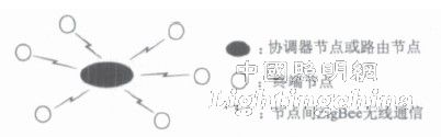
Figure 1 system network model diagram
In Figure 1, the coordinator node or routing node is the central control node of the system, and communicates with each terminal node through the ZigBee protocol. In this system, terminal nodes are divided into three categories according to different functions: terminal nodes that collect indoor light intensity, terminal nodes that collect personnel position movement information, and terminal nodes that control lighting modes.
3 system hardware design
As can be seen from the foregoing, at the functional level, the system includes four types of nodes: a central control node composed of a coordinator node or a routing node, a terminal node that collects indoor light intensity, a terminal node that collects the location information of the person, and control The terminal node of the lighting mode. These nodes must have corresponding hardware support to implement their respective functions.
For the central control node, a microcontroller running the ZigBee protocol stack and a wireless transceiver are required. If you need to connect to a PC, the central control node needs to be configured with the corresponding interface. For example, the system uses the PIC18F4620 microcontroller and CC2420 transceiver, and configures the RS2232 serial interface for the central control node.
The terminal node that collects the indoor light intensity and the terminal node that collects the location movement information of the person must configure the corresponding sensor in addition to the single chip microcomputer and the wireless transceiver that run the ZigBee protocol stack. The system is equipped with a light sensor for the former and an infrared sensor for the latter.
Finally, the terminal node that controls the illumination mode also needs the basic single-chip and transceiver components. In addition, an external thyristor control circuit is needed, as shown in Figure 2, for adjusting the brightness of the illumination.
This circuit is designed according to the idea of ​​AC zero-crossing detection [7]. The microcontroller shown in Figure 2 is indirectly powered by AC, so an inductor T1 is required to achieve circuit separation. In addition, diodes D1~D4 are responsible for controlling waveform correction; capacitor C2 is used for ripple filtering; C3 is as close as possible to the microcontroller power supply pin to suppress high frequency noise; Zener diode (Z1) provides the desired modulation voltage by compressing the rectified voltage. If the MCU is not powered indirectly by using AC power, the left half of Figure 2 can be omitted and can be directly powered by an external DC power supply. The two optocouplers in the right half of Figure 2 isolate the load from the high voltage control circuit. The PB6 pin of the MCU is used to collect each zero crossing of the AC sinusoidal period, and PD0 is used to control the conduction of the suspendable silicon.
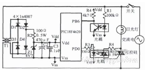
Figure 2 Dimming circuit based on PIC18F4620 microcontroller
4 system control process
Chapter 2 points out that the system consists of a central control node, a terminal node that collects indoor light intensity, a terminal node that collects the location information of the person, and a terminal node that controls the lighting mode. In the system control, the terminal node responsible for collecting the indoor environment information sends the collected light intensity information, the number of indoor personnel and the position information to the central control node, and the central control node first comprehensively processes the information to determine the current indoor The illumination mode should be set, and then the illumination mode is sent to the terminal node controlling the illumination mode, and the terminal node controlling the illumination mode drives the external thyristor circuit according to the received illumination mode information, and finally sets the brightness and dark condition of the corresponding illumination lamp. . When the indoor environment information changes, the system can automatically sense these conditions and switch to the corresponding lighting mode.
In the specific implementation process, the following problems need to be solved: the judgment of personnel entering and leaving the room; the judgment of the position information of the personnel; the judgment of the intensity of the indoor light; the design of the external thyristor circuit driving method; and the design of the lighting mode of the central control node.
The above problems are discussed below in conjunction with specific examples. As shown in Figure 3, an example of each node of the system is arranged indoors. The upper side of the room entrance is numbered 0 as the central control node; the two nodes numbered Ñ and Ò are the terminal nodes, which are used to collect the personnel entering the room. The two terminal nodes A and B are used to collect the light intensity information in the current room; the nodes responsible for collecting the position information of the personnel in the room are terminal nodes 5, 6, 7, and 8; the remaining X and Y Z three terminal nodes are used to control the setting of the room lighting mode, in which the X node controls the top of the room, the Y node controls two wall lamps next to the rectangular table, and the Z node controls the desk lamp on the desk.
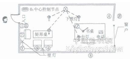
Figure 3 System node layout model diagram
4.1 Judgment method for personnel entering and leaving the room
The judgment of the personnel entering and leaving the room is realized by two terminal nodes carrying infrared sensors, such as two nodes numbered Ñ and Ò in FIG. During the specific implementation process, the MCU pins connected to the sensor are configured as double-edge triggered interrupts. In this way, only when Ñ and Ò have successively generated rising edge interrupts, and then successively generate falling edge interrupts, it is considered that someone has entered the room, as shown in the entry state in Figure 4; likewise, when someone leaves the room, Ò and Ñ successively rise. Along the interrupt, then the falling edge interrupt is generated successively, as shown in Figure 4; for other interrupt trigger situations, the number of people in the current room is not changed, as shown in Figure 4, the exit and fallback states.
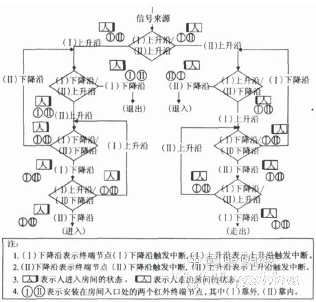
Figure 4 Control flow chart for judging people entering and leaving the room
In this example, two terminal nodes are used to judge the situation of people entering and leaving the room. The advantage of this is that the two sensor probes can be placed closest to each other, thereby avoiding the interruption of the rising edge of the crucible due to the far distance of the two sensors. Along the interrupt, Ò then the rising edge is interrupted, that is, the person has passed the sensor Ñ, but has not yet triggered the result to the sensor Ò. The disadvantage of this method is that the computational burden of the central control node is increased because both terminal nodes need to send the sensed interrupt signal to the central control node without any processing.
Another method is to use a terminal node to complete the judgment control of the personnel entering and leaving the room, and requires two infrared sensors to be connected to the pin on the terminal node to generate a double edge interrupt. The advantage of this method is that the calculation process of judging personnel entering and leaving the room is completed by the terminal node itself, which reduces the computational burden of the central control node; the disadvantage is that the two infrared sensor probes cannot be too close, otherwise it is easy to generate an interrupt processing process, and the other The interruption of the arrival of the situation affects the accuracy of the judgment results.
4.2 Judgment of indoor location information of personnel
The discrimination of the indoor personnel position information is realized by a terminal node carrying infrared sensing. According to the detection distance of the infrared sensor and the size of the indoor space, the number and specific position of the infrared terminal nodes can be reasonably arranged. As shown in FIG. 3, the nodes numbered 5-8 are infrared terminal nodes for indoor positioning. The specific implementation method is relatively simple and will not be described again.
4.3 Determination of indoor light intensity
The indoor light intensity judgment is realized by a terminal node carrying a photosensor. The system uses two terminal nodes carrying photosensitive sensors, corresponding to the A and B nodes in the window of Figure 3. Taking into account the characteristics of the photosensitive sensor itself and the specific needs of people, the two terminal nodes carrying the photosensitive sensors are placed outdoors, and one place is placed indoors when people pull the curtains to block them.
The main reason for placing a node outdoors is that the light sensor can sense the brightness of the indoor light itself. Therefore, if the photosensitive sensor is installed indoors to sense the illumination light line, when the illumination light is on, the photosensitive sensor will get a light intensity, which causes the routing node to turn off the illumination, and then sense the light. As a result of the darkness, the illumination light is set again, causing the indoor illumination mode to cycle between light and dark.
Place a terminal node carrying a light-sensitive sensor in a place where indoor curtains can be blocked, mainly to maximize the satisfaction of people's needs. For example, when the indoor person pulls the curtains during the day, the indoor photosensitive sensor senses the dark result, and then triggers the illumination mode in which the illumination light is set to avoid the result that the interior is dark when the curtain is pulled up during the day.
Finally, for the results sensed by the two photosensors, a larger (black) value is always selected as the effective value.