Abstract: This application note and application note 3936, "Maxim USB Library 'is used together. Application note 3936 mainly describes a hardware and software system for simplifying the development of built-in USB embedded hosts and peripherals. In this system, MAX3421E is the host , MAX3420E is a peripheral. This application note explains how to use the EV kit to set up the hardware, and gives three methods of evaluating the software.
Introduction In conjunction with application note 3936, the "Maxim library" describes the construction of C programs and Keil ™ project files for a USB host (MAX3421E) and peripherals (MAX3420E) under the same ARM®-based hardware environment. The evaluation system hardware includes the following parts: MAX3421E EVKIT-1 Keil MCB2130 downloadable software.
This application note explains how to configure the various components of this evaluation board.
Other Materials and Contact Information Information about the MAX3420E and MAX3421E can be downloaded from the Maxim website. You can obtain data materials, other application notes about the Maxim USB library, other application notes related to the MAX3420E and MAX3421E, and ways to apply for samples.
If you have questions about the MCB2130 circuit board or Keil Software®, ARM software development tools, please contact Keil :.
Hardware Configuration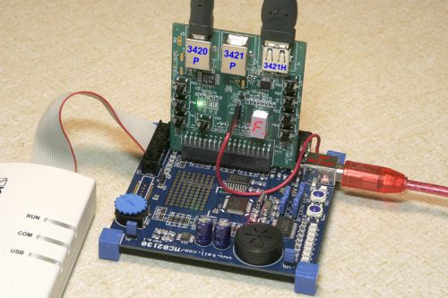
Figure 1. The Maxim MAX3421E EVKIT-1 is inserted into the Keil MCB2130 circuit board.
Figure 1 shows a dual-board configuration, where the blue one is the Keil MCB2130 board, including a Philips® LPC2138, ARM7 ™ microcontroller. LPC2138 provides two SPI hardware units, each unit is connected to a USB controller.
The circuit board placed vertically in Figure 1 is the MAX3421E EVKIT-1. As shown in Figure 1, the MAX3420E peripheral controller is connected to one of the ARM SPI ports, and is connected to the USB B port (J5) labeled "3420P" (P stands for peripheral). The MAX3421E host / peripheral controller connects to another ARM SPI port and connects to the interfaces labeled “3421P†(J2) and “3421H†(J1) (H represents the host). Because the USB library program uses the MAX3421E as the host, the USB interface (J2) in the middle of the evaluation board is not used.
MCB2130 (P1) has two serial interfaces. The host program uses one of them to send the USB description information to the PC running the terminal emulation program. A terminal program, such as Tera Term Pro, can emulate the terminal (VT100), recognize the special "escape" sequence sent by the program, clear the screen and move the cursor to the starting position. The terminal program is set to 38400, N, 8, 1, without flow control.
The beige box and cable in Figure 1 are Keil ULINK ™ JTAG download debuggers, supported by the Keil µVision3 development environment. The MCB2130 board comes with µVision3 evaluation program (full-featured version of Keil toolbox). The evaluation board limits the program code to 16kB.
There are four USB interfaces in the dual-board configuration, and the USB interface on the Keil MCB2130 board is only connected to VBUS and ground. Plug this interface into a USB host to provide 5V power to the dual-board system. Some USB hubs may not provide enough current to drive the board, so it is best to take power directly from the PC's spare USB port.
There are three USB ports on the Maxim evaluation board. As mentioned above, port B is connected to the MAX3420E. Figure 1 is labeled 3420E P. The MAX3421E (either as a USB host or as a peripheral) is connected to two USB ports (3421P and 3421H). These interfaces connect the D + and D- pins together, and only one is connected at a time. The USB library program does not use the middle USB port (3421P).
The MAX3420E and MAX3421E are connected to two independent SPI ports of the ARM microcontroller. This configuration makes it easy to write to the host and peripherals running the same program at the same time, while also providing an ideal USB training and debugging system. The host can send the USB request to the peripheral device, the peripheral device generates a response, the host then evaluates the result, and all operations are in a C program. The black USB cable in Figure 1 is used to connect the MAX3420E and MAX3421E.
Keil MCB2130 board can be obtained from Keil and other sources. The above Maxim web page provides the latest information on Keil products.
MAX3421E EVKIT-1 block diagram
Figure 2. MAX3421E EVKIT-1 structure block diagram, the elliptical shaded part is the application module.
Figure 2 provides two USB controller and USB port connection (J1, J2, J5). Insert the 36-pin plug (J4) into the Keil MCB2310 development board. This design uses two independent SPI ports of the ARM processor to facilitate independent operation of the two USB controllers (U1 and U2). The host program runs in the background (the program in main {}), and the peripheral program is called by LPC2138 interrupt EINT0.
Because U1 operates as a host, the system must provide power VBUS to the USB A port (J1). By connecting to the flying lead of J3-3, we provide 5V power to the evaluation board. The 5V power supply can be derived from the test point marked "5V IN" on the Keil board, or it can be provided by a laboratory power supply. U3 (MAX4793) controls the on and off of VBUS and provides current limiting. U3 controls VBUS to supply power to J1 through its GPO-7 pin, and can detect the overcurrent of GPIN-0 (over 300mA).
The buttons and indicators on the evaluation board are connected to two controllers. U1 drives a 7-segment digital tube and connects to 4 buttons (PB1-PB4). U2 drives 4 LEDs and connects to buttons PB5 to PB8.
Keil MCB2130 board preparation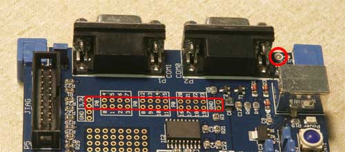
Figure 3. Install the 36-pin plug to the area indicated by the red frame
The Keil MCB2310 board is designed for mounting multiple 2-pin and 8-pin connectors (Figure 3). The Maxim evaluation board is connected to the Keil MCB2310 through a 36-pin plug (included on the board), which includes 3.3V power pins, three sets of 8-pin connectors, and two GND pins (shown in the red line area in Figure 3). Because there is a gap between the connectors on the Keil board, some pins should be removed before installing the 36-pin connector. After making sure that the unnecessary pins have been removed from the connector, install the plug on the Keil board.
Figure 3 shows a detection point (red circle, in the upper right part of the board). From this point, the 5V power supply required by the Maxim evaluation board can be derived. This 5V power actually comes from the VBUS pin of the USB power interface on the Keil board (Figure 4).
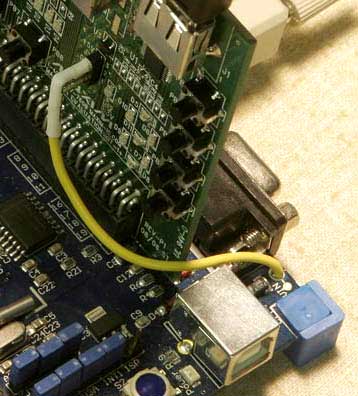
Figure 4. VBUS is provided for the Maxim evaluation board via flying leads.
Keil software installation Keil µVision3 ARM development software demo version can be downloaded from, the µVision3 project file provided with the Maxim software package is created by the downloadable Keil file tool mdk303a.exe. Since there are two project files provided by Keil in its development environment, this version of the project file must be used (these two files are not included in the MaximUSBLab10.zip file). The MaximUSBLab project file is installed under the path C: \ Keil. When installing the Keil demonstration toolbox, the default installation directory C: \ Keil must be used to ensure the correct path of the Keil file.
For the mdk303a.exe toolbox in Keil, the two file path names provided by Keil are:
C: \ Keil \ ARM \ RV30 \ Boards \ Keil \ MCB2130 \ Blinky \ startup.s
C: \ Keil \ ARM \ RV30 \ Boards \ Keil \ MCB2130 \ Blinkyetarget.c
The Keil demo project includes many versions of "Blinky". Be sure to use the file corresponding to the MCB2310 board. Maxim's software uses the MCB2310.
If you have Keil ULINK JTAG debugging unit, you need to download USB driver from Keil website. The Maxim program has been tested using the 3071.zip file (downloaded from the Keil website). After installing the demo version of µVision development software, double-click the file to install the USB driver and connect µVision3 to the ULINK unit.
After installing the demo version of Keil software, find the MaximUSBLab10 folder and double-click the file MaximUSBLab.Uv2. This will open the project file under the correct settings. Click the "Rebuid All Target Files" button to compile the project file. If you have a ULINK unit and installed a USB driver, you can click the "Star / Stop Debug Session" button to run, modify, and debug Maxim routines.
Three ways to run firmware download and view MaximUSBLab.hex
The Maxim USB library (hex) file can be downloaded from the Maxim website. It is included in application note 3936, "Maxim USB library, which is part of the Keil compressed project file. The hex file can be downloaded through a free plug-in (Flash Magic, shown in Figure 5). Download to the LPC2138 flash memory, the plug-in is available on the. Before using the plug-in, check the instructions under OpTIons / Advanced OpTIons / Hardware Config.
On the Keil board, when running the Flash Magic plug-in, use the P2 serial interface and connect J7 to the ISP.
Note: After removing J7, S2 will no longer be the source of INT1 interrupt. Since the Maxim application uses INT1 for other purposes, you can put J7 on the ISP.
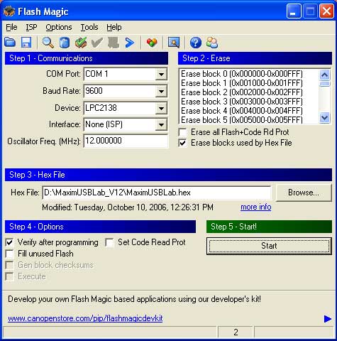
Figure 5. Typical settings of Flash Magic for MCB2310
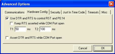
Figure 6. Set options first
Commissioning and modification (restricted)
If you have a Keil ULINK JTAG unit, you can compile the Maxim sample code, download and debug it through the JTAG interface. You can also set breakpoints and step through the code. This is a good way to learn USB quickly-study and modify the working host and / or peripheral device code to meet our purpose.
The demo version of Keil µVision3 for ARM has all the functions of µVision3, and the code size is limited to 16kB. The Maxim USB Library project file (MaximUSBLab.Uv2) is compiled in "Thumb only" mode to ensure that the capacity of the project code is within the limits.
Full development For formal development work, it is recommended to purchase the full-featured Keil µVision3 ARM toolbox. This can be used without limitation of 16kB, and is suitable for a wider range of applications (up to 512kB LPC2138 flash memory).
Introduction In conjunction with application note 3936, the "Maxim library" describes the construction of C programs and Keil ™ project files for a USB host (MAX3421E) and peripherals (MAX3420E) under the same ARM®-based hardware environment. The evaluation system hardware includes the following parts: MAX3421E EVKIT-1 Keil MCB2130 downloadable software.
This application note explains how to configure the various components of this evaluation board.
Other Materials and Contact Information Information about the MAX3420E and MAX3421E can be downloaded from the Maxim website. You can obtain data materials, other application notes about the Maxim USB library, other application notes related to the MAX3420E and MAX3421E, and ways to apply for samples.
If you have questions about the MCB2130 circuit board or Keil Software®, ARM software development tools, please contact Keil :.
Hardware Configuration
Figure 1. The Maxim MAX3421E EVKIT-1 is inserted into the Keil MCB2130 circuit board.
Figure 1 shows a dual-board configuration, where the blue one is the Keil MCB2130 board, including a Philips® LPC2138, ARM7 ™ microcontroller. LPC2138 provides two SPI hardware units, each unit is connected to a USB controller.
The circuit board placed vertically in Figure 1 is the MAX3421E EVKIT-1. As shown in Figure 1, the MAX3420E peripheral controller is connected to one of the ARM SPI ports, and is connected to the USB B port (J5) labeled "3420P" (P stands for peripheral). The MAX3421E host / peripheral controller connects to another ARM SPI port and connects to the interfaces labeled “3421P†(J2) and “3421H†(J1) (H represents the host). Because the USB library program uses the MAX3421E as the host, the USB interface (J2) in the middle of the evaluation board is not used.
MCB2130 (P1) has two serial interfaces. The host program uses one of them to send the USB description information to the PC running the terminal emulation program. A terminal program, such as Tera Term Pro, can emulate the terminal (VT100), recognize the special "escape" sequence sent by the program, clear the screen and move the cursor to the starting position. The terminal program is set to 38400, N, 8, 1, without flow control.
The beige box and cable in Figure 1 are Keil ULINK ™ JTAG download debuggers, supported by the Keil µVision3 development environment. The MCB2130 board comes with µVision3 evaluation program (full-featured version of Keil toolbox). The evaluation board limits the program code to 16kB.
There are four USB interfaces in the dual-board configuration, and the USB interface on the Keil MCB2130 board is only connected to VBUS and ground. Plug this interface into a USB host to provide 5V power to the dual-board system. Some USB hubs may not provide enough current to drive the board, so it is best to take power directly from the PC's spare USB port.
There are three USB ports on the Maxim evaluation board. As mentioned above, port B is connected to the MAX3420E. Figure 1 is labeled 3420E P. The MAX3421E (either as a USB host or as a peripheral) is connected to two USB ports (3421P and 3421H). These interfaces connect the D + and D- pins together, and only one is connected at a time. The USB library program does not use the middle USB port (3421P).
The MAX3420E and MAX3421E are connected to two independent SPI ports of the ARM microcontroller. This configuration makes it easy to write to the host and peripherals running the same program at the same time, while also providing an ideal USB training and debugging system. The host can send the USB request to the peripheral device, the peripheral device generates a response, the host then evaluates the result, and all operations are in a C program. The black USB cable in Figure 1 is used to connect the MAX3420E and MAX3421E.
Keil MCB2130 board can be obtained from Keil and other sources. The above Maxim web page provides the latest information on Keil products.
MAX3421E EVKIT-1 block diagram
Figure 2. MAX3421E EVKIT-1 structure block diagram, the elliptical shaded part is the application module.
Figure 2 provides two USB controller and USB port connection (J1, J2, J5). Insert the 36-pin plug (J4) into the Keil MCB2310 development board. This design uses two independent SPI ports of the ARM processor to facilitate independent operation of the two USB controllers (U1 and U2). The host program runs in the background (the program in main {}), and the peripheral program is called by LPC2138 interrupt EINT0.
Because U1 operates as a host, the system must provide power VBUS to the USB A port (J1). By connecting to the flying lead of J3-3, we provide 5V power to the evaluation board. The 5V power supply can be derived from the test point marked "5V IN" on the Keil board, or it can be provided by a laboratory power supply. U3 (MAX4793) controls the on and off of VBUS and provides current limiting. U3 controls VBUS to supply power to J1 through its GPO-7 pin, and can detect the overcurrent of GPIN-0 (over 300mA).
The buttons and indicators on the evaluation board are connected to two controllers. U1 drives a 7-segment digital tube and connects to 4 buttons (PB1-PB4). U2 drives 4 LEDs and connects to buttons PB5 to PB8.
Keil MCB2130 board preparation
Figure 3. Install the 36-pin plug to the area indicated by the red frame
The Keil MCB2310 board is designed for mounting multiple 2-pin and 8-pin connectors (Figure 3). The Maxim evaluation board is connected to the Keil MCB2310 through a 36-pin plug (included on the board), which includes 3.3V power pins, three sets of 8-pin connectors, and two GND pins (shown in the red line area in Figure 3). Because there is a gap between the connectors on the Keil board, some pins should be removed before installing the 36-pin connector. After making sure that the unnecessary pins have been removed from the connector, install the plug on the Keil board.
Figure 3 shows a detection point (red circle, in the upper right part of the board). From this point, the 5V power supply required by the Maxim evaluation board can be derived. This 5V power actually comes from the VBUS pin of the USB power interface on the Keil board (Figure 4).
Figure 4. VBUS is provided for the Maxim evaluation board via flying leads.
Keil software installation Keil µVision3 ARM development software demo version can be downloaded from, the µVision3 project file provided with the Maxim software package is created by the downloadable Keil file tool mdk303a.exe. Since there are two project files provided by Keil in its development environment, this version of the project file must be used (these two files are not included in the MaximUSBLab10.zip file). The MaximUSBLab project file is installed under the path C: \ Keil. When installing the Keil demonstration toolbox, the default installation directory C: \ Keil must be used to ensure the correct path of the Keil file.
For the mdk303a.exe toolbox in Keil, the two file path names provided by Keil are:
C: \ Keil \ ARM \ RV30 \ Boards \ Keil \ MCB2130 \ Blinky \ startup.s
C: \ Keil \ ARM \ RV30 \ Boards \ Keil \ MCB2130 \ Blinkyetarget.c
The Keil demo project includes many versions of "Blinky". Be sure to use the file corresponding to the MCB2310 board. Maxim's software uses the MCB2310.
If you have Keil ULINK JTAG debugging unit, you need to download USB driver from Keil website. The Maxim program has been tested using the 3071.zip file (downloaded from the Keil website). After installing the demo version of µVision development software, double-click the file to install the USB driver and connect µVision3 to the ULINK unit.
After installing the demo version of Keil software, find the MaximUSBLab10 folder and double-click the file MaximUSBLab.Uv2. This will open the project file under the correct settings. Click the "Rebuid All Target Files" button to compile the project file. If you have a ULINK unit and installed a USB driver, you can click the "Star / Stop Debug Session" button to run, modify, and debug Maxim routines.
Three ways to run firmware download and view MaximUSBLab.hex
The Maxim USB library (hex) file can be downloaded from the Maxim website. It is included in application note 3936, "Maxim USB library, which is part of the Keil compressed project file. The hex file can be downloaded through a free plug-in (Flash Magic, shown in Figure 5). Download to the LPC2138 flash memory, the plug-in is available on the. Before using the plug-in, check the instructions under OpTIons / Advanced OpTIons / Hardware Config.
On the Keil board, when running the Flash Magic plug-in, use the P2 serial interface and connect J7 to the ISP.
Note: After removing J7, S2 will no longer be the source of INT1 interrupt. Since the Maxim application uses INT1 for other purposes, you can put J7 on the ISP.
Figure 5. Typical settings of Flash Magic for MCB2310
Figure 6. Set options first
Commissioning and modification (restricted)
If you have a Keil ULINK JTAG unit, you can compile the Maxim sample code, download and debug it through the JTAG interface. You can also set breakpoints and step through the code. This is a good way to learn USB quickly-study and modify the working host and / or peripheral device code to meet our purpose.
The demo version of Keil µVision3 for ARM has all the functions of µVision3, and the code size is limited to 16kB. The Maxim USB Library project file (MaximUSBLab.Uv2) is compiled in "Thumb only" mode to ensure that the capacity of the project code is within the limits.
Full development For formal development work, it is recommended to purchase the full-featured Keil µVision3 ARM toolbox. This can be used without limitation of 16kB, and is suitable for a wider range of applications (up to 512kB LPC2138 flash memory).
CCTV Baluns,Video Balun Transceiver Transmitter,Passive Video Balun,HD CCTV Video Balun
Chinasky Electronics Co., Ltd. , https://www.chinaskyswitches.com