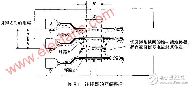
 The basic mutual inductance coupling of the current loop in operation is illustrated in Figure 9.1. The current leaves gate A and flows back to the source via signal return path X. Since the current paths X, Y, and Z overlap each other, the magnetic field of path X will induce a noise voltage on signal paths Y and Z.

Since the overlapping area of ​​the path Y and the path X is larger than the overlapping area of ​​the path X path X, the induced noise on the path Y is larger than the induced noise on the path Z. In fact, the generation of mutual inductance noise does not require the paths to completely overlap, and any two adjacent current loops will affect each other.
There are also parasitic capacitances between the pins of the connector, but in digital circuits, the crosstalk caused by parasitic capacitance is less than the crosstalk caused by mutual inductance. Now let's focus on the larger part of the problem: inductance.
1. Estimating crosstalk
For the magnitude of signal crosstalk between any of the signal pins in Figure 9.1, an estimate typically requires three conditions.
Mutual inductance between two current loops
Maximum rate of change of source signal DI/DT
Receive network impedance and whether it is terminated at the source or end
Considering the mutual inductance between the two loops, we need to find the worst case crosstalk, so the following focuses on the interaction between two directly overlapping loops, such as loop X and loop in Figure 9.1. Y.
The total magnetic energy in loop Y comes from two aspects: first, the current flowing from gate A and along the signal line, and secondly, the return signal current along the ground. Therefore, the mutual inductance formula includes two items, and the second item (ground line item) is larger than the first item:
(Formula 1)
Where: A = distance from signal X to signal Y, IN
B = distance from signal Y to ground, IN
C = distance of signal X to ground, IN
D = diameter of the connector pin, IN
H = connector pin length, IN
LX, Y = mutual inductance between loops X and Y, NH
The above formula assumes that the connectors are single-row and the pins are relatively long. Even if these assumptions are not true, due to the nature of the logarithmic function, it is easy to obtain an accurate result within an order of magnitude from the above equation, which is sufficient to accurately determine whether the crosstalk characteristics of the connector are a significant problem. If the characteristics of the connector are related to the performance of the system, then buy a connector and test its performance.
The problem to be discussed below is the maximum value of DI/DT in the system. We use equation () or equation () to estimate DI/DT.
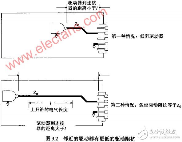
The last condition relates to the noise acceptance circuit topology. Figure 9.2 shows the chosen solution: In the first case, the drive is connected next to the connector, where “close†means that the distance from the drive to the connector is within the electrical length of a rising edge, see equation () . The second case covers all other structural forms, including source termination.

In the structure corresponding to the second case, the coupling noise is split in half in both directions. In the first case, the coupled noise is quickly reflected at the low impedance drive, doubling the coupling noise at the receiver.
The equation below gives the height of the noise pulse induced on loop Y due to a single step input from gate A. The duration of this pulse is comparable to the rising edge time of the input pulse.
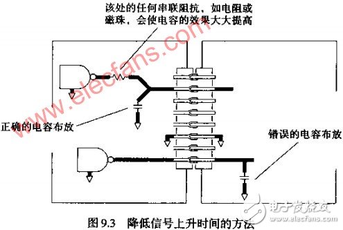
Slowing the rising edge of the drive signal can directly reduce crosstalk. As shown in Figure 9.3, paralleling the capacitor at the source of the connector reduces the rise time of the drive signal. If a capacitor is placed at the receiving end, the inrush current flowing through the connector will only increase when the driver signal jumps, making the situation worse.

2. How to change the return current path by grounding
The following five criteria for connector characteristics, combined with Equation 1, can help estimate the performance of the connector with different ground arrangements. These guidelines are effective when making calculation adjustments to a system. At the same time, using these guidelines, we can predict what will happen when different changes are proposed.
Criterion 1 In Figure 9.1, the mutual inductance between specific lines can be reduced by changing the grounding mode. If the ground line is moved further away from the loops X and Y, that is, the values ​​of B and C are increased, the two terms in Equation 1 will increase, and the mutual inductances LX and Y will increase. Conversely, bringing the ground line close to the loops X and Y will reduce their mutual inductance. The change in mutual inductance is proportional to the logarithm of the distance.
The additional land of Guideline 2 will have a more direct effect. Remember that the second item (ground line item) in Equation 1 is the largest. Since the ground line is tightly coupled to the loops X and Y, the current on the ground has a large effect on the loop Y. If we can divide the current on the ground into two halves, the mutual inductance LX and Y will be reduced by half.
As shown in Figure 9.4, by adding a ground line above the signal X, the current on the ground line is divided into two halves, and the current is divided into two parts, which flow through each ground line. Accordingly, the mutual inductances LX and Y are also reduced. Adding more ground will further disperse the ground current, but will not split the current into two as originally.

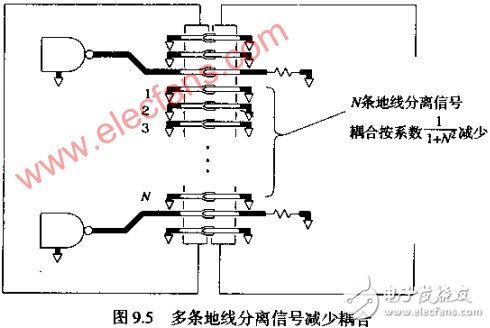
Criterion 3 Inserting ground lines between signals X and Y is quite different from adding ground lines outside of them. If we add N ground lines between X and Y, as shown in Figure 9.5, the spacing between the two increases, and the coupling between them decreases proportionally. The coupling is proportional to:

Criterion 4 is coupled to any given line noise on the connector from each of the other lines. Simply reducing the number of signals on the connector reduces the overall crosstalk. On the other hand, the signals on the connector are divided into groups. Interference between the groups can be reduced by inserting a ground line between the groups. Packets effectively reduce the number of lines that cause severe crosstalk to a particular receiver, which is substantially proportional to the number of signal lines between the ground lines.
Criterion 5 Adding additional ground to the edge of the connector reduces crosstalk and hardly works, as does the large grounding effect on the edge of the connector.
Brushed Stainless Steel Plate,Hot Rolled Brushed Stainless Steel Plates,Dimple Plate Stainless Steel,Professinal Dimple Plate Stainless Steel
ShenZhen Haofa Metal Precision Parts Technology Co., Ltd. , http://www.haofametals.com