The PLC is a transistor output type. The output unit allows the load to work with DC 12-24 V. Yufa can directly drive the AC contactor. It can only pioneer the DC 12-24 V intermediate relay, and then use the intermediate relay to drive the AC 380 V load, this will make the external wiring cumbersome, and because the traditional AC contactor is an electromagnetic switch, the life and reliability of its mechanical contacts are far from the PLC control system, which greatly hinders the control system performance Play. Therefore, for such loads, we need to choose a more suitable relay to act as its controlled switching device.
1 Characteristics and classification of solid state relays1.1 The characteristics of solid state relays
Solid state relay SSR is an emerging control relay in the world in recent years. This kind of relay can control the start and shutdown of high-power loads with a tiny signal of a few milliamps, which is in line with the characteristics of transistor output PLC. And its input signal (control terminal) and output signal (controlled terminal) adopt photoelectric isolation circuit to ensure that the input and output do not interfere with each other, the output terminal adopts non-contact high-power output circuit, and the whole circuit is cast with epoxy resin as a whole . Therefore, solid state relays have no sparks, noise, pollution, and electromagnetic interference during operation. Compared with electromagnetic relays, they have faster switching speed, smaller size, long life, shock resistance, corrosion resistance, moisture resistance, and corrosion resistance. The advantages of tremor, etc., can be used in severely polluted and vibrated environments, and have high sensitivity and anti-interference ability. They are widely used in petrochemical equipment, lighting equipment, textile machinery, CNC lathes, entertainment facilities, etc. This kind of automatic control field is especially suitable for harsh environments such as corrosion, dust prevention, explosion-proof requirements, and frequent switching occasions.
1.2 Classification of solid state relays
AC solid state relays are divided into voltage zero-crossing conduction type and random conduction type according to the switching mode; according to the output switching element, they are divided into triac output type (ordinary type) and one-way SCR anti-parallel type (enhanced type); According to the installation method, it is divided into the pin type used on the printed circuit board (natural cooling, no radiator) and the device type fixed on the metal bottom plate (cooled by the radiator); in addition, the input end has a wide range input (DC 3 ~32 V) constant current source type and series resistance current limiting type.
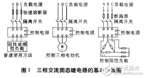
Single-phase SSR is a four-terminal active device. Two input control terminals and two output terminals are optically isolated between input and output. After the input terminal adds a DC or pulse signal to a certain current value, the output terminal can be switched off. Turn into the on-state. The three-phase AC solid-state relay integrates three single-phase AC solid-state relays, and uses a single input terminal to directly switch the three-phase load, which can easily control the 1-phase AC motor, heater and other three-phase loads. Figure 1 shows the basic wiring diagram of a three-phase AC solid state relay. The phase and phase of the three-phase AC solid state relay, the insulation voltage between the input and output, and the substrate are greater than 2 000 VAC, and other basic indicators are the same as the corresponding single-phase solid state relay. It should be pointed out that for occasions where the actual load current is not large, such as laboratory teaching, the three-phase SSR is more convenient to use, but when the current is large, the heat will also be large. At this time, using three single-phase SSRs is more reliable.

2.1 Three-phase AC motor forward and reverse control circuit controlled by PLC
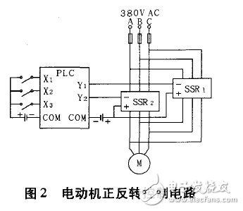
Figure 2 is a PLC-controlled three-phase AC motor forward and reverse control circuit, where X1, X2, and X3 respectively represent the input of the PLC and control the rotation direction and start and stop of the motor; Y1, Y1 represent the output of the PLC. When Y1 is valid, SSR1 input terminal gets DC24V DC signal, then the three-phase output terminal changes from off state to on state, three-phase AC motor is energized and reversed; in the same way, when Y is valid, the three-phase output terminal of SSR2 is connected If A and c are reversed, the motor will rotate forward.

2.2 PLC controlled Y-â–³ step-down starting control circuit
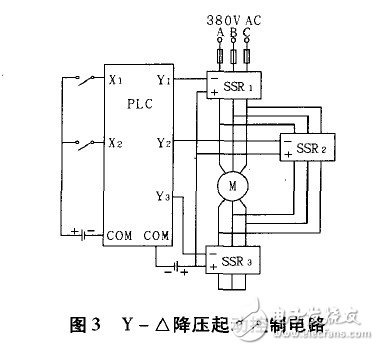
Figure 3 is a PLC controlled Y-â–³ step-down starting control circuit, where X1 and X2 respectively represent the input of the PLC and control the start and stop of the motor; Y1, Y2, and Y3 represent the output of the PLC. When Y1 and Y3 are valid, the corresponding SSR1 and SSR3 are also valid at the same time. At this time, the motor is Y-connected. After a few seconds, Y3 is invalid and Y2 is valid, then the corresponding SSR3 three-phase output is disconnected, and SSR2 three When the phase output terminal is closed, the motor becomes â–³ connection, and Y-â–³ step-down starting is completed.

The three-phase AC solid-state relay is a collection of three single-phase AC solid-state relays. It uses a single input terminal to directly switch the three-phase load, and can use a few milliamps of tiny signals to control the start and cut off of the high-power load. Device. It has been verified that it can control three-phase AC motors, heaters and other three-phase loads reliably, safely and conveniently, and makes the external wiring of PLC simple.
Combining the very latest technologies with proven RF experience, our 1000W FM Transmitter has been designed to offer an innovative and highly reliable solution for medium power transmission.
The FM 1000W is highly robust and delivers efficiency of up to 72%. Top signal quality and performance are achieved thanks to the [FM band direct to frequency" Digital Modulator. It also offers several innovative features such as dynamic RDS encoding and 5 band sound processing.
1000W Fm Transmitter,1000W Fm Radio Transmitter,1000W Fm Radio Transmitter System,1000W Professional Fm Broadcast Transmitter
Anshan Yuexing Technology Electronics Co., LTD , https://www.yxhtfmtv.com