Xilinx's Vivado HLS tool helps reduce the rising cost of wireless fronthaul network infrastructure.
The huge challenge for wireless network operators is to increase the capacity and density of the network while maintaining the bottom line of profit and loss. The compression scheme for the wireless interface can reduce the required investment in the infrastructure of the fronthaul network and help meet this challenge.
We use the high-level synthesis (HLS) tool of the Vivado ®Design Suite to evaluate the Open Radio Equipment Interface (ORI) standard compression scheme for E-UTRA I/Q data to estimate its impact on signal fidelity and the resulting time Extension and its implementation cost. We found that Xilinx's Vivado HLS platform can efficiently evaluate and implement the selected compression algorithm.
Wireless bandwidth pressureThe continuous increase in wireless bandwidth requirements has given rise to the demand for new network functions, such as higher-order MIMO (Multiple Input Multiple Output) configurations and carrier aggregation. This has led to increasingly complex networks, requiring operators to make structural adjustments, such as centralized baseband processing to optimize the use of network resources. While reducing the cost of baseband processing, the sharing of baseband processing resources will increase the complexity of the fronthaul network.
These fronthaul networks are responsible for transmitting antenna carrier modulation signals between the baseband unit (BBU) and the remote radio unit (RRH). Using the Common Public Radio Interface (CPRI) protocol on the optical fiber is the most common way to implement this network. The CPRI protocol requires a constant bit rate, and after years of development, the protocol specification has increased the maximum data rate to meet the ever-increasing demand for bandwidth. Network operators are looking for the right technology to be able to significantly increase the data rate while not increasing the number of fibers used, so as to maintain the current capital expenditures and operating expenditures of cellular base stations.
To provide long-term solutions, network operators are studying alternative network layouts, including redesigning the interface structure between baseband processing and radio units to reduce the fronthaul bandwidth. However, the rearrangement of network functions may make it more difficult to meet the stringent performance requirements of some wireless interface specifications.
Another way to reduce bandwidth is to implement a compression/decompression (codec) scheme for wireless interfaces that are close to or exceed the available throughput. The achievable compression rate depends on the specific wireless signal characteristics, such as noise level, dynamic range, and oversampling rate.
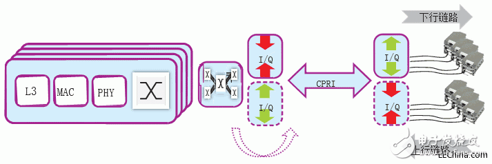
Let us take a closer look at the ORI standard compression scheme for E-UTRA IQ data-the real and virtual components of the transmission modulation symbols. The simplified application example in Figure 1 illustrates the location of the compression and decompression modules in the CPRI IQ input and output interfaces. The specific channel characteristics are explored during the filter design process to minimize the signal loss caused by the following downsampling and upsampling .
IQ compression algorithmThe ORI standard is improved and improved on the basis of the CPRI specification, and aims to support the open BBU/RRH interface. In the latest version, ORI specifies lossy time-domain E-UTRA data compression technology for channel bandwidths of 10, 15 or 20 MHz. Combining fixed 3/4 rate resampling with non-linear quantization of 15-bit IQ samples can reduce bandwidth requirements by 50%. For example, it helps to achieve 8 x 8 covering two partitions through a single 9.8 Gbps CPRI link MIMO configuration.
The resampling stage involves interpolating the input I and Q data streams, passing the interpolated data through a low-pass filter, and decimating the output data stream. In the filter design process, the specific channel characteristics are explored to minimize the signal loss caused by the down-sampling and up-sampling stages. For example, a 20 MHz E-UTRA downlink channel sampled at a 30.72 MHz rate can output an effective OFDMA bandwidth of 18.015 MHz, which means that an ideal lossless low-pass filter response can be achieved at a 3/4 sampling rate.
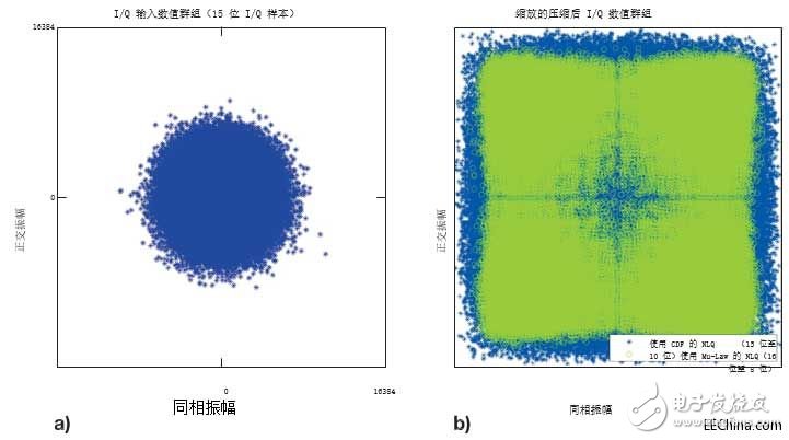
The non-linear quantization (NLQ) process converts a normally distributed 15-bit baseband IQ sample into a 10-bit quantized value. NLQ uses a cumulative distribution function (CDF) with a specified standard deviation to describe the amplitude of a higher frequency (rather than a lower frequency) at fine granularity, in order to minimize the quantization error. As shown in the result in Figure 2b, the filling ratio of the quantized value group to the reduced value range is significantly higher than that of the input value group shown in Figure 2a. Therefore, compared with other linear quantization schemes, the quantized value group The group can minimize the quantization error. Usually, I and Q samples are implemented in a look-up table, and they are individually quantified using their corresponding distribution functions. We compare the ORI IQ compression performance with the Mu-Law compression algorithm implementation plan specified by ITU-T RecommendaTIon G.711. It is also a non-linear quantization technology, Mu-Law uses a logarithmic function to redistribute the quantized value within the available numerical range. Different from the CDF quantization method that considers the statistical distribution of input samples, the output quantized by Mu-Law is a function of the corresponding input sample value and the specified compression value.
In order to compare the equivalent compression ratio of 50%, we consider 16-bit to 8-bit Mu-Law encoders. Since no resampling is required, Mu-Law compression is a low-cost solution in terms of latency and implementation resource costs, which can be a trade-off between design complexity and achievable reconstructed signal fidelity.

Figure 1-Simplified wireless system using CPRI IQ compression technology

The 20 MHz E-UTRA DL channel refers to the IQ value group (a) of the input frame, and the compressed IQ data (b) is expanded to illustrate each value group. ..
Figure 2–20 MHz E-UTRA DL channel reference input frame IQ value group (a), and compressed IQ data (b) expanded to illustrate the use of the effective value range of each value group
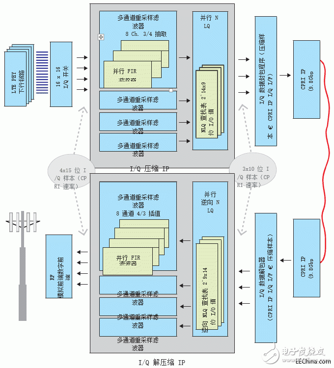
Scale up the codec architectureFor the prototype configuration, we plan to scale up the compression algorithm to take full advantage of the 9.8304 Gbps CPRI link (line bit rate option 7). The ORI compressed E-UTRA sample specification allows us to transmit 16 compressed IQ channels (32 I and Q channels are compressed separately) through a single 9.8G CPRI link. The target throughput is three compressed samples for each CPRI clock, which is enough to fully package the 32-bit Xilinx LogiCOREâ„¢ IP CPRI IQ interface to provide the required 737.28 Msps of compressed IP output.
With a single clock domain as the goal, we need to build a resampling filter to meet the output rate of three samples per clock cycle. Interpolating the input sample stream with 0's complement allows us to ignore useless input samples. The output stream becomes a function of the interpolation rate of the subfilters, and each subfilter uses a subset of FIR coefficients (the total number of coefficients/interpolation rate). There are a total of four parallel filters, each running on a subset of channels, making the overall throughput equivalent to requiring 3 compressed samples per clock cycle. In addition to high throughput, the proposed architecture can also reduce the resampling delay because only a small percentage of coefficients are used in each sub-filter.
For the compression path, we use the cumulative distribution function (CDF) to calculate the NLQ quantization table. Assuming that the IQ distribution is symmetric, we reduce the size of the NLQ lookup table to 214 9-bit quantized values. Since our design requires three parallel lookup tables per clock cycle, we use the same quantization value to implement three parallel lookup tables. can
Use the expected or observed standard deviation values ​​to calculate the quantification level separately for the I and Q samples. Or, based on actual signal-level measurements or higher-level network parameters, a subset of channels can be quantified separately. When decompressing, we use the quantile function (inverse CDF) to calculate the inverse NLQ table. The size of the table is limited to 29 14-bit values.
We use the 20 MHz LTE E-UTRA FDD channel stimulus generated by the MATLAB® LTE system toolbox to test the implemented encoding and decoding algorithms. Then, we use Keysight VSA to demodulate the captured IQ data, and measure the output waveform error vector magnitude (EVM) to quantify the signal distortion caused by the compression and decompression stages. We compare the published measured value of the output EVM (which reflects the difference between the ideal signal and the measured signal) with the reference input signal EVM.
Advanced modeling and implementation processWe use GNU Octave language, and use its signal processing and statistics package to develop a single-channel compression and decompression model, and start the implementation process. In addition to providing useful reference data points for verification, the model output also generates a set of FIR filter coefficients and quantization tables.
The Vivado HLS tool provides an obvious transmission path from the high-level mathematical model, and evaluates the proposed architecture in terms of potential hardware performance and cost. We have built a C++ test bench to use compression and decompression functions to perform operations on the input data stream. Since we will place these functions on the opposite end of the CPRI link, we will synthesize them separately. Using the HLS stream and the interleaved channel data stream under simple C++ cycle management, we have implemented all internal and external function interfaces.

The IQ codec architecture shows (in downlink only) the sample processing rate at the codec IP interface
Figure 3 – IQ codec architecture shows the sample processing rate at the IP interface of the codec (downlink only)
We use Vivado HLS FIR IP to develop the prototype design of the resampling filter. To meet the high throughput requirements of the design, we implemented a parallel single-rate FIR filter and adopted a loop-based filter output decimation function.
By implementing a polyphase resampling filter, a more efficient resource-saving resampling filter can be obtained. The multi-channel hierarchical sampling rate conversion filter is an out-of-the-box option that supports the ORI resampling rate; Xilinx Application Note XAPP1236 "Using Vivado high-level synthesis for multi-channel hierarchical sampling rate conversion filter design." The filter is introduced.
When the verification data set is large, the advantages of fast C-level simulation become more obvious. This is best reflected in the evaluation of IQ compression algorithms, because at least a complete radio data frame (307,200 IQ samples/channel) is required to use the VSA tool for EVM measurements. We found that C simulation can increase the simulation speed by two orders of magnitude compared with C/RTL co-simulation; for this compressed IP test, compared to the 9 hours of co-simulation running time, C simulation only takes 5 minutes.
The HLS test bench also has another important advantage, that is, the use of files and HLS streams can easily use input data and capture output data. As a result, an interface can be provided for data analysis using VSA tools, or directly compared with Octave model output in a C++ testbench.
Performance measurementKeysight VSA measurement results show that a codec configuration with 144 FIR coefficients has an average EVM of 0.29%. Compared with the initial input data with an EVM RMS of 0.18%, the extra EVM part due to the compression-decompression processing chain is 0.23%. In contrast, the average EVM achieved by the Mu-Law compression algorithm under the same input data set is 1.07%.
According to the time delay and resource usage cost reduced by the Mu-Law compression method, when 1% of the 8% EVM budget of the entire LTE downlink signal processing chain can be allocated to IQ compression, Mu-Law compression will be better than ORI IQ compression scheme. However, any additional signal distortion means setting stricter performance targets for the remaining system components. The increased cost of components such as digital front-end components and power amplifiers may offset potential IQ compression cost advantages.
Vivado high-level synthesis confirmed the required throughput based on the startup interval—the number of clock cycles before the top-level task was ready to accept new input data. At the same time, after our verification, the exported Vivado IP Integrator core meets the timing requirements of the target Kintex® UltraScale™ platform.
We limit the research scope to a small number of configurations and input data vectors. However, once the system model and corresponding C language model are in place, alternative configurations can be customized, implemented, and evaluated in minutes.
Design alternativesFrom the perspective of design tools, Vivado HLS provides a viable path for hardware prototyping. The advanced test platform is very suitable for design frameworks that need to transmit data streams between multiple design and verification tools. The main advantage of this test platform is that it can quickly perform C language simulation on the hardware system model. For IQ compression and similar applications, the simulation runtime involves frequent changes in advanced parameters or input data sets, making rapid feedback an important factor.
Measurement results show that the proposed ORI compression scheme can achieve signal distortion of less than 0.25% for the 20 MHz E-UTRA downlink channel. Although the compression performance depends on the input channel characteristics, the ORI compression scheme can still select the best combination of filter design and quantizer parameters to provide a range of performance adjustments.
Our prototype design uses a common static design parameter set for all 16 antenna carrier data streams. In a real system, the signal characteristics can be known in advance, or they can be measured and used to adjust the design. Alternatively, the compression performance can be dynamically adjusted by reconfiguring the quantization table to maintain the required minimum signal fidelity.
In addition to compression performance, the implementation resources required to perform compression and decompression and the costs caused by additional delays must also be considered. Resampling filter size and delay account for the main part of the total codec cost; larger EVM tolerance should allow for designs with fewer filter coefficients.
Taking into account the time-to-market factor, Xilinx created a proof of concept based on the ORI-based IQ codec.
Servo Drives,Ac Servo Motor,Digital Motor Driver,Brushless Motor Driver
Zhejiang Synmot Electrical Technology Co., Ltd , https://www.synmot-electrical.com