In order to overcome the influence of nonlinear and uncertain factors of permanent magnet synchronous motor (PMSM) servo system and improve the control precision and performance characteristics of servo system, fuzzy-proportional, integral and derivative (PID) control with correction factor is proposed. It is a control system that combines the advantages of PID control and fuzzy control. It determines whether the speed controller adopts the fuzzy control algorithm or the PID control algorithm according to the rotational speed deviation, and uses the correction factor to blur according to the rotational speed deviation and the speed error rate of the control system. The parameters of the controller are modified online. The simulation results show that the fuzzy-PID control with correction factor optimizes the dynamic and static characteristics of the system and meets the high performance requirements of the system. The superiority and reliability of the control strategy are verified.
The servo system is a kind of automatic control system. The closed-loop control structure is usually used to control a certain state of the controlled object, so that it can automatically, continuously and accurately reproduce the change law of the input signal, which is often used in fast and precise positions. Control and speed control applications. With the rapid development of modern industry, higher and higher requirements are placed on control accuracy and reliability. To this end, a variety of control methods have been proposed, the most common of which are proportional, integral and differential (PID) control methods, which have simple algorithms, good stability, wide application range, mature theory and wide application and industrial control fields. A linear constant parameter system that can be used to model accurate mathematical models. However, the actual permanent magnet synchronous motor (PMSM) itself has nonlinearity, time-varying, uncertain factors, etc. It is difficult to establish an accurate mathematical model, and the system is also subjected to different degrees of interference during operation, so the PID control strategy is difficult to meet the high-performance PMSM servo. System control requirements.
Compared with the traditional PID control method, the fuzzy control does not depend on the accurate mathematical model of the controlled object, and has strong robustness to the dynamic response of the system, but it is difficult to eliminate the stability error when the system is adjusted, and the PID control method can be A good solution to this deficiency. Therefore, the combination of the two can effectively solve the shortcomings of fuzzy control with steady state error. However, the fuzzy controller with fixed parameters cannot guarantee that the dynamic and static characteristics of the system are optimal over a wide range. In order to improve the performance of the fuzzy controller, the parameters of the fuzzy controller are modified online according to the rotational speed error e and the speed error rate ec of the control system, that is, the correction factor.
l Design of Fuzzy-PID controller
1.1 System Control Structure
The servo system speed controller consists of two parts: the fuzzy controller and the PID controller. The controller determines which control algorithm the speed controller uses to achieve speed closed loop control based on the speed deviation e. When the speed deviation e is greater than the threshold ε, the response speed of the system should be increased at this time, and the control action should be increased to make the actual rotor speed reach the given speed as soon as possible. At this time, the fuzzy control algorithm should be adopted; when the speed deviation e is smaller than the valve When the value ε, the rotor speed is close to the given speed. At this time, the static characteristics of the system should be improved to improve the steady-state accuracy of the system. In this case, the PID control algorithm should be adopted. At the same time, for the fuzzy control controller, taking into account the dynamic and static characteristics of the system, the parameters of the coarse adjustment and fine adjustment are self-adjusting, thus solving the contradiction between the adjustment speed and the steady-state accuracy.
Figure 1 shows the principle of fuzzy PID speed control. The input variable of the two-dimensional fuzzy controller is the difference between the speed reference and the speed feedback e and the error variation ec output variable is the given u of the current loop. And define:
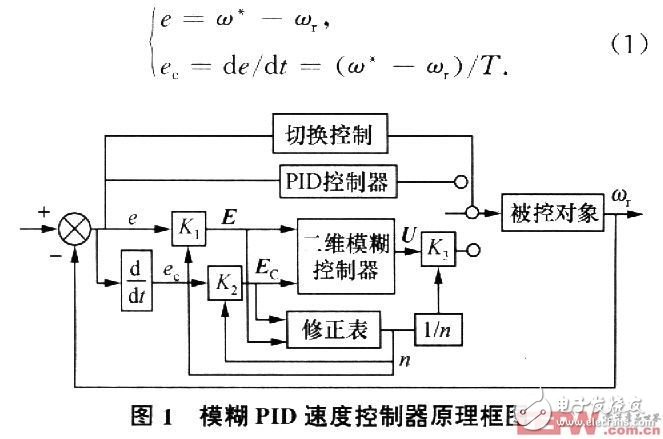
1.2 Control rules
The selection of fuzzy rules is the core of designing fuzzy controllers. The input and output of fuzzy controllers are linked by fuzzy control rules table, and the selection of fuzzy inference rules is based on the error and error rate. When the error is large, the control quantity is selected to eliminate the error as soon as possible; when the error is small, the selection of the control quantity is based on the steady state of the system, and attention should be paid to prevent overshoot, and the selected membership function curve is sharper and the control is controlled. The higher the sensitivity. To this end, the normal distribution function is selected as the membership function of the fuzzy variable, and the center of gravity method is used for fuzzy decision.
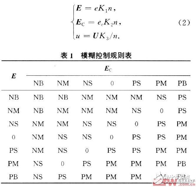
Let the basic domain of E and Ec in Fig. 1 be [1-6,6], and blur the error and error rate of change to 13 levels, that is, E=Ec={一å…,一五,一四,一三, One 2, one l, O, l, 2, 3, 4, 5, 6}. The field of the velocity fuzzy controller output U is [0,6] and is divided into 7 quantization levels, namely U={1,2,3,4,5,6); the E, Ec and U fuzzy sets are {negative large (NB), negative medium (NM), negative small (NS), zero (0), positive small (PS), medium (PM), Zhengda (PB)}. According to experience, the control rules of the fuzzy controller can be summarized, as shown in Table 1. The result in the table is the output U obtained by fuzzy logic inference when the input quantity is E and Ec. These rules are essentially a series of "IF-THEN" type fuzzy conditional statements which are summarized by the operator's control experience. . The predecessor of the conditional statement is the input variables E and Ec, and the latter is the output variable U.
The quantization factors of the speed deviation e and the speed deviation change ec are respectively K1 and K2: the scale factor of the output U is K3. These three factors also have a direct impact on the control results. K1 is too large to overshoot and is prone to limit cycles. Too small will make the response time of the system longer. The larger K2 is, it will help to suppress overshoot and oscillation, but it is too large. The system should be slower, and if K2 is too large or too small, the overshoot will increase and the limit cycle will easily occur. The determination of K3 has a great influence on the control performance of the fuzzy controller. Its choice is related to the actual control object. If K3 is too small, the dynamic response process of the system will become longer. If K3 is too large, the overshoot will become larger and the system will oscillate. In order to make the system response fast and without overshoot, the parameter factors K1, K2 and K3 are usually modified online, thereby correcting the relationship between the basic domain e, ec and "with the domains E, Ec and U.
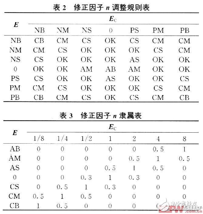
The adjustment principle of the correction factor n is: when e and ec are large, the system should reduce the deviation and speed up the dynamic process. At this time, a larger control amount should be selected, that is, increase K3, decrease K1 and K2; when e and ec When it is small, that is, when the system is close to the steady state value, then K3 should be reduced, K1 and K2 should be increased, the overshoot should be reduced, and the steady state accuracy of the system should be improved.
Let the correction factor be n, the fuzzy variable be N, and the fuzzy set be {high release (AB), middle release (AM), low release (AS), constant (OK), small reduction (CS), medium reduction ( CM), large contraction (CB); N's domain N={1/8, 1/4, 1/2, 1, 2, 4, 8}. The original quantization factor and the scale factor of the basic fuzzy controller are respectively obtained. According to the quantized E and Ec, the correction factor is obtained. The adjustment rule table and the membership table of the correction factor n are respectively shown in Table 2 and Table 3. The control rules are substantially similar to Table 1. . At this time, the quantization factor and the scale factor are adjusted to:
2 system simulation model
This system uses Simulink simulation module with powerful MATLAB7.0 to simulate. The PMSM parameters are set in the simulation as follows:
Stator resistance R = 2.875 Ω; armature inductance Ld = Lq = 8.510-3H; flux φ = 0.175 Wb; pole pair p = 4. And set the motor at O. The torque was changed from 4 Nm to 7 Nm at 2 s; the speed was given at 700 r/min. Figure 2 shows the system simulation block diagram.
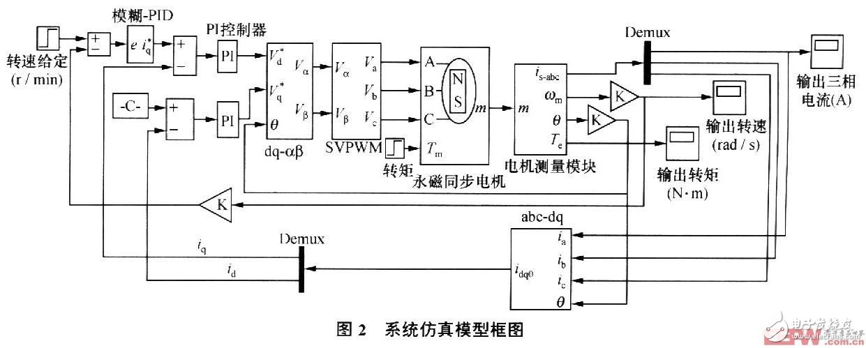
This system uses a digital signal processor (DSP) based all-digital AC servo system. In this way, the control functions can be implemented in the DSP through software programming without the need to build additional hardware circuits, making the entire system structure simple and compact. Moreover, the full digital control makes the servo system more reliable, and the control parameters are easier to adjust than the hardware circuit.
The system mainly includes:
1) a magnetic pole position detecting module and a current detecting module;
2) speed loop and current loop control;
3) coordinate transformation module;
4) Space Vector Pulse Width Modulation (SVPWM) module;
5) Rectifier and inverter modules.
The power module driver in the system adopts the most commonly used pulse width modulation (PWM) optimization method SVPWM, which can significantly reduce the harmonic component of the inverter output current and the harmonic loss of the motor, and reduce the ripple torque. With the development of DSP technology, the enhancement of computing functions and the increase of storage capacity, the digitalization of PWM is more and more convenient.
The current loop uses a PI control algorithm, the speed loop uses a fuzzy-PID control, and the current regulator and speed regulator use a PI regulator with saturation limiting.
The feedback value of the current loop armature current is compared with the current command signal to obtain the current error. The current loop regulator adjusts and controls according to the error, so that the current quickly follows the command value change, and the current has no static difference at steady state. The rotated/stationary coordinate system outputted by the current controller is transformed into Vα and Vβ in the stationary coordinate system, and then the voltages Va, Vb and Vc of the three-phase winding of the motor are obtained through the power driving module; the detected winding current passes through the stationary/rotating coordinate system. Transform to id and iq in the rotating coordinate system.
The speed error of the speed command signal and the speed feedback signal in the speed loop is adjusted and controlled by the speed regulator according to the speed error, so that the motor speed quickly follows the command value change, the steady state speed has no static difference, and the dynamic speed limit overshoot, Greatly reduce the impact of load changes on the speed change. At the same time, due to the negative feedback of the rotational speed, the angular velocity of the rotor is detected and the actual rotational speed of the rotor is obtained through coefficient conversion. Detecting variables and reference variables
The latter error is used as the input to the speed loop and current loop, thus forming a closed loop control of the entire system.
3 system simulation results
In order to compare PID control and Fuzzy-PID control performance, Figure 3 and Figure 4 show the speed step response when PID control and Fuzzy-PID control are used respectively.
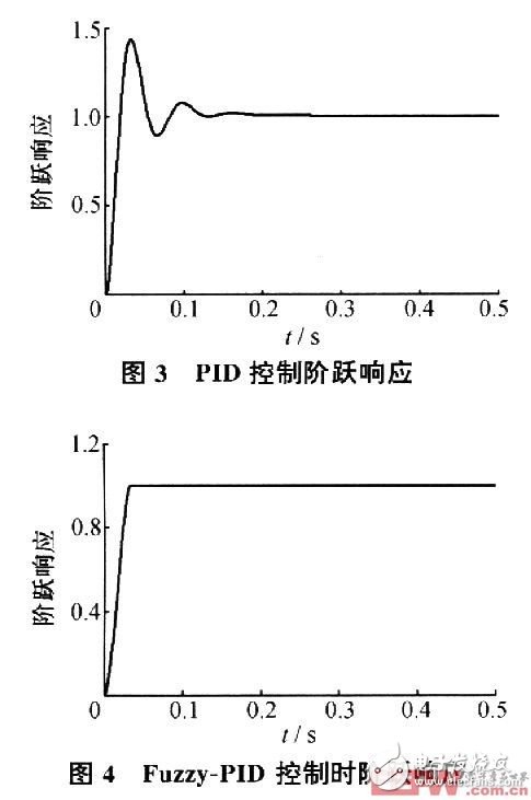
It can be seen from the figure that when PID control is adopted, the speed will overshoot and oscillate, which will cause great impact during motor starting; after using Fuzzy-PID, there is no overshoot and oscillation, and the system is robust. The response speed has improved significantly.
Fig. 5 and Fig. 6 are simulation diagrams of the torque Te and the rotational speed n when the system is controlled by Fuzzy-PID). It can be seen from the figure that when the load torque suddenly increases from 4Nm to 7Nm at 0.2 s, the torque is quickly adjusted to a new stable value; at the same time, due to the continuous adjustment of SVPWM, the torque ripple is small; and the rotational speed is at O. When it is 2 s, it drops slightly, and then quickly restores the original speed.
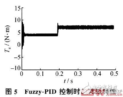

It can be seen that the control strategy adopted by the system has the characteristics of good tracking performance, fast response, short transition time, no overshoot, good stability and high control precision, which is consistent with the previous theoretical analysis.
4 Conclusion
In this paper, the combination of fuzzy control and PID control is applied to the PMSM AC servo control system, which not only avoids the limitation of the complex mathematical model of the controlled object when designing the controller, but also overcomes the time-varying and strong coupling of the servo system. And the influence of uncertainty factors improves the system response speed and control accuracy, and the tracking performance is good. In addition, in order to improve the performance system control of the fuzzy controller, the correction factor is used to modify the parameters of the fuzzy controller online, which ensures the system has good dynamic and static performance and robustness, which proves the correctness and feasibility of the method. .
Fiber Optic Accessories,Fiber Optic Cable Connectors,Fiber Optic Adapter,Fiber Cable Connectors
Huizhou Fibercan Industrial Co.Ltd , https://www.fibercannetworks.com