Double acting cylinder (with magnetic switch)
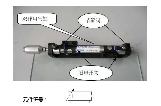
How to use: Adjust the throttle valve to adjust the operating speed of the cylinder. The left throttle throttle cylinder retracts and the right throttle valve cylinder protrudes. The magnetic switch (near-look switch) is used to detect the position of the cylinder. When the cylinder is retracted, the right magnetic switch is turned on, whereas the left is turned on. When the magnetoelectric switch is used, no power can be applied directly to both ends, and it is required to be connected in series to the load (by means of the red lamp at the + end).
Single acting cylinder
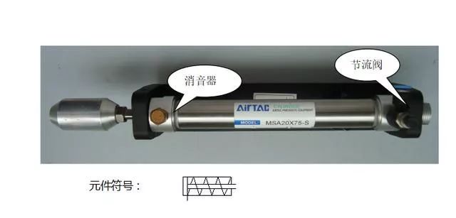
How to use: Adjust the throttle valve to adjust the operating speed of the cylinder. When there is gas passing through the throttle valve, the cylinder will extend; otherwise, the cylinder will retract (automatically reset by the spring).
Two-position five-way single solenoid valve
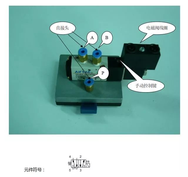
The three direct heads are connected to the trachea end, which are P inlets, A: A outlets, and B: B outlets. When P has gas A position out of gas (that is, the initial position of the solenoid valve), when the solenoid valve coil is energized (DC24V small lamp at the positive), solenoid valve commutation, B position gas. When the solenoid valve coil is de-energized, it returns to its initial position through the spring.
Two-position five-pass double solenoid valve
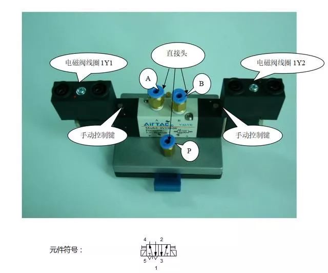
The three direct heads are connected to the trachea end, which are P inlets, A: A outlets, and B: B outlets. When the P port has gas, the gas outlet at the previous gas outlet is still out of gas (ie, the position where the last solenoid valve was energized). When the solenoid valve coil 1Y1 is energized (the DC24V lamp is positive), the solenoid valve is reversed. A mouth gas. When the solenoid valve coil 1Y2 is energized (DC24V small lamp is positive), the solenoid valve changes direction, and B outlets. This position is retained after the solenoid is de-energized.
Three five-way double solenoid valve
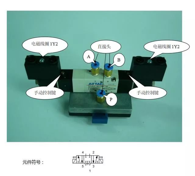
The three direct heads are connected to the trachea end, which are P inlets, A: A outlets, and B: B outlets. When the P port is gas and the coil of the solenoid valve is not energized, it is reset under the action of the springs on both sides, and there is no air out of ports A and B. The valve remains in the neutral position. When solenoid valve coil 1Y1 is energized (DC24V small lamp is positive), solenoid valve reversal, A outlet gas. When the solenoid valve coil 1Y2 is energized (DC24V small lamp is positive), the solenoid valve changes direction, and B outlets. After the coil of the solenoid valve is de-energized, the valve body is automatically reset under the action of the springs on both sides, and there is no air out of the ports A and B. The valve remains in the neutral position.
Electrical signal limit switch
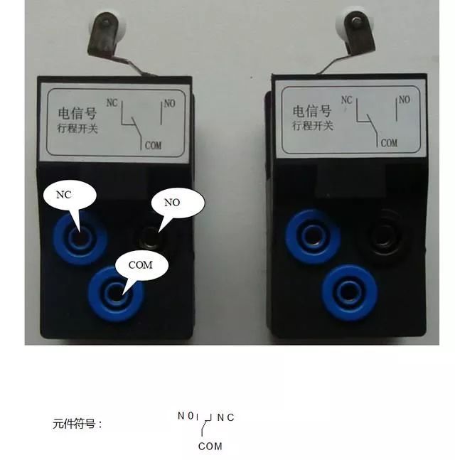
The element is used to detect the position of the cylinder, and is placed on the retracted and extended positions of the cylinder, respectively, so that they contact the cylinder probe to operate. When the white roller end pops up, the COM terminal is connected to the NC and NO is disconnected. When the white roller end is depressed by the cylinder probe, COM and NO are open and NC is disconnected. Two electrical signal travel switches are paired to detect the left and right seats of the cylinder.
Capacitive sensor
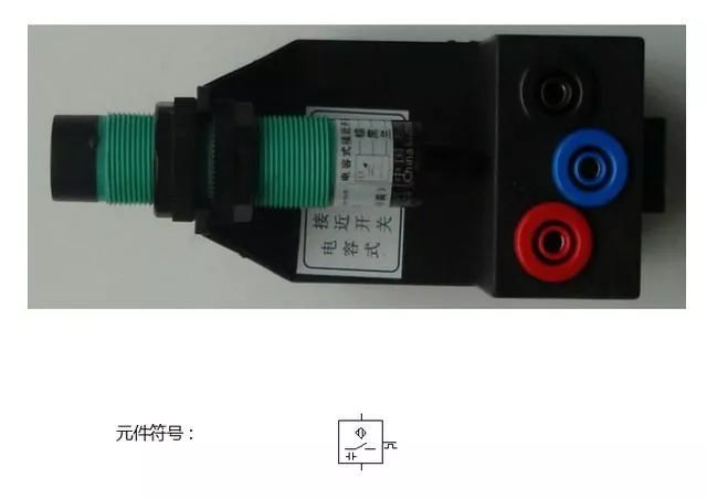
Sensor wiring method: red circle connected DC24V, black circle connected to DC0V, blue circle for the output. When the sensor senses the signal, this point outputs the signal (the signal level depends on the sensor type, NPN type is output DC0V, PNP type is output DC24V). When using, pay attention to the correctness of the wiring, to prevent damage to the components, especially the output terminal short-circuit phenomenon is the most serious.
The capacitive sensor, also known as a proximity switch, senses anything that is close to its range. The detection range is generally between 0.8-1CM (adjustable).
Photoelectric Sensors
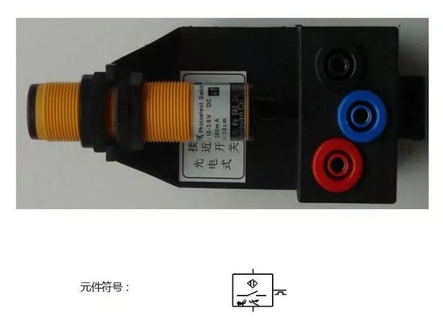
Sensor wiring method: red circle connected DC24V, black circle connected to DC0V, blue circle for the output. When the sensor senses the signal, this point outputs the signal (the signal level depends on the sensor type, NPN type is output DC0V, PNP type is output DC24V). When using, pay attention to the correctness of the wiring, to prevent damage to the components, especially the output terminal short-circuit phenomenon is the most serious.
Photoelectric sensors detect objects that reflect enough light to sense them. The detection range is generally about 6CM. Due to this characteristic, we can use the reflection of different objects to adjust the distance, indirectly to achieve the detection of color.
Inductive sensor
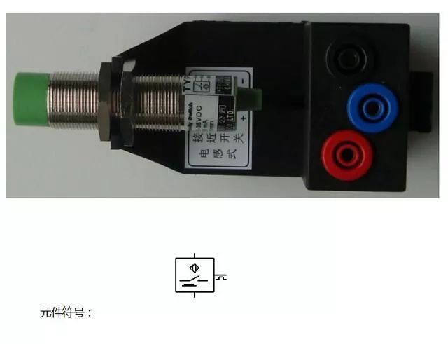
Sensor wiring method: red circle connected DC24V, black circle connected to DC0V, blue circle for the output. When the sensor senses the signal, this point outputs the signal (the signal level depends on the sensor type, NPN type is output DC0V, PNP type is output DC24V). When using, pay attention to the correctness of the wiring, to prevent damage to the components, especially the output terminal short-circuit phenomenon is the most serious.
Inductive sensors are used to detect metal materials. The detection range is generally about 1CM. Compared with the above two sensors, it is relatively stable and will not be interfered by some other items and produce false signals because it has a short detection distance and is only valid for metal objects.
Gas-to-electricity converter
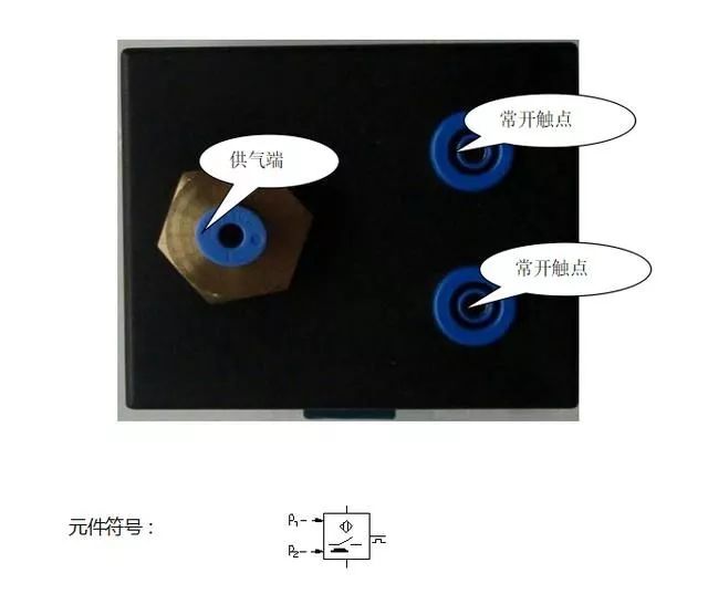
As the name suggests, this component converts the pneumatic signal into an electrical signal. The air intake causes the internal mechanical action of the component. The normally open contact becomes the normally closed contact. It is generally chained to act as a control signal in the circuit.
Emergency stop switch
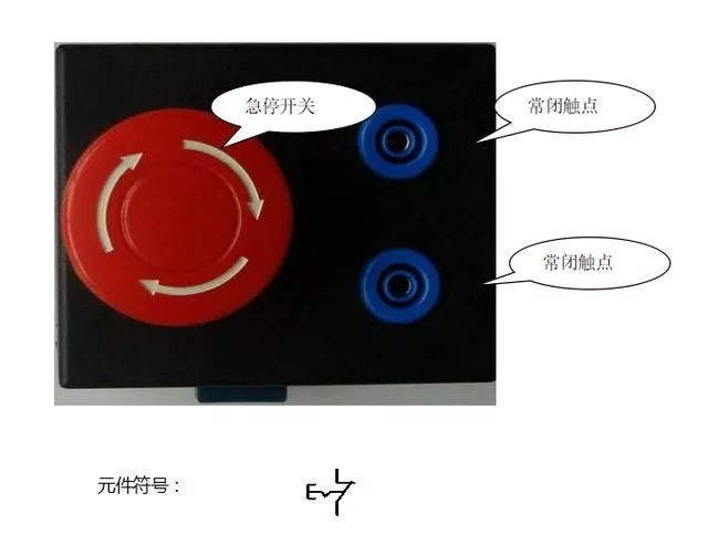
Connect the normally closed contact of the element into the main circuit (power-on circuit). If an error occurs in the loop, press the red button to stop the entire circuit from working. Rotate in the direction indicated by the white arrow on the button surface, and the emergency stop is released, and the power-on operation can be continued.
Manual reversing valve
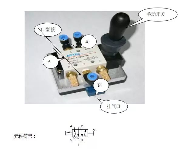
The L-type connector is used to connect the gas pipe mouth. After the P port is supplied with air, the air inlet and outlet of the A and B ports are controlled by pulling the manual switch. When the circuit is switched, exhaust is performed through the exhaust port.
Check valve
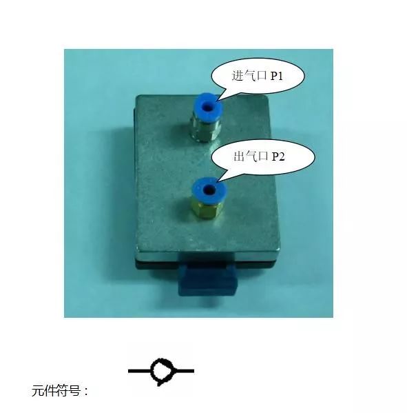
When the air inlet P1 has gas, the air outlet P2 is vented. Conversely, when the air outlet P2 is ventilated, the air inlet P1 is airless, that is, so-called one-way.
One-way throttle valve
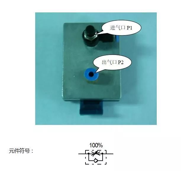
When air inlet P1 is vented, the adjustment knob can control the outlet flow of P2.
Pneumatic display
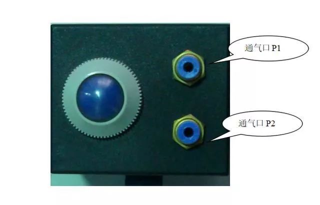
The P1 and P2 ports of the component are serially connected to the pneumatic circuit to detect whether the circuit is working properly and whether the vents enter or exit the air. When the gas in the circuit passes, the indicator light is red, otherwise it is blue.
Pressure gauge
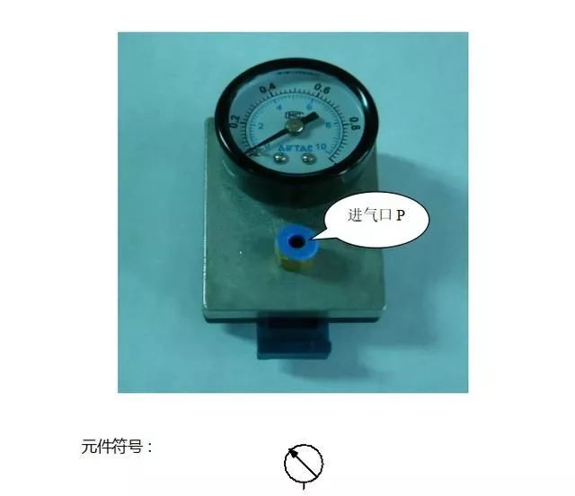
The element is connected to a node in the loop to detect the pressure value at that point, which is mainly used to monitor the pressure of the node.
Pressure regulator

The element is connected to a loop, and the pressure of the loop at that point can be adjusted. P1 is the air inlet and P2 is the air outlet. If the P1 and P2 ports of the component are reversed, a sound will be generated inside the component. Pull up the black knob and rotate in the direction of the arrow to adjust the outlet pressure. In principle, the outlet pressure should be less than the inlet pressure.
Air control delay valve
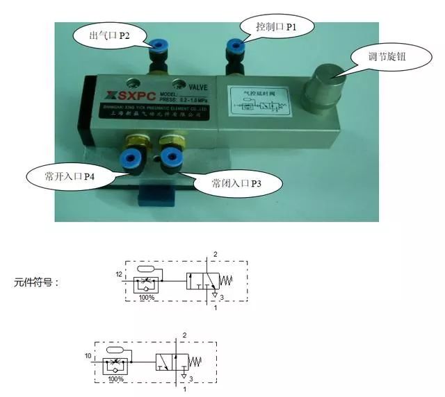
The above symbol is normally open and the following symbol is normally closed.
The components we provide are available in both modes, but only one of them can be used at a time. When the air inlet P4 is normally open, the control port P1 is ventilated, and after a delay of N seconds (realized by the adjusting knob), the P2 outlet is vented. When the air inlet P3 is normally closed, the control port P1 is ventilated, and the P2 port first has a gas output, and after a delay of N seconds (realized by the adjustment knob), the P2 port is air-locked.
Two-position three-way button type reversing valve
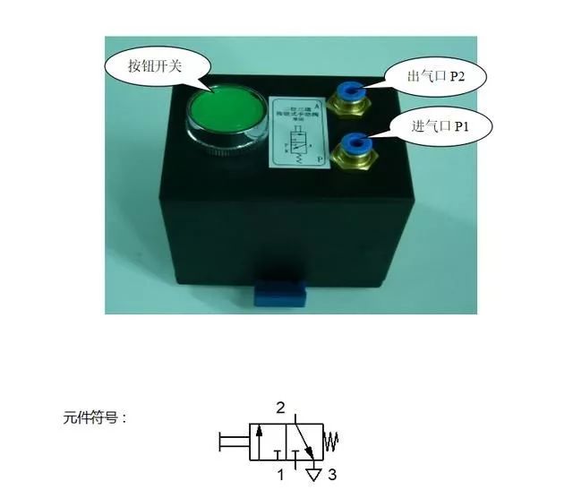
When the air inlet P1 is ventilated, the button switch is pressed, and the air outlet P2 is ventilated. This element is usually used as a starting button string in the loop.
Two-position five-way single air control valve
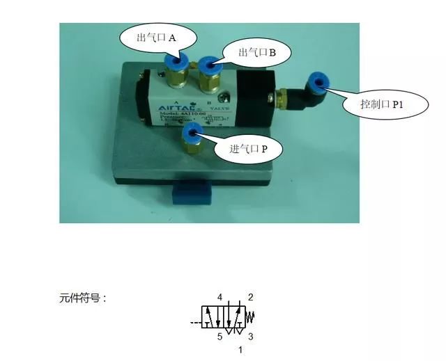
When the air inlet P is ventilated, when the control port P1 has no gas, the air outlet A has a gas output. When the control port P1 is ventilated, the air outlet B has a gas output, and the air outlet A is disconnected. When control port P1 again disconnects gas, the valve relies on its own spring to return to the initial position.
Two-position five-way dual air control valve
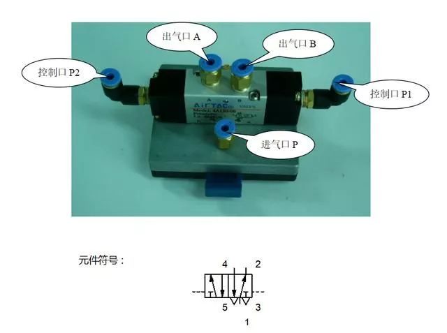
When the air inlet P is ventilated, no gas passes through the air outlets A and B, and the air in the previous state A or B is still maintained. When the control port P1 is ventilated, the gas outlet B has a gas output; whereas when the control port P2 is ventilated, the gas outlet A has a gas output.
Three-position five-way dual air control valve
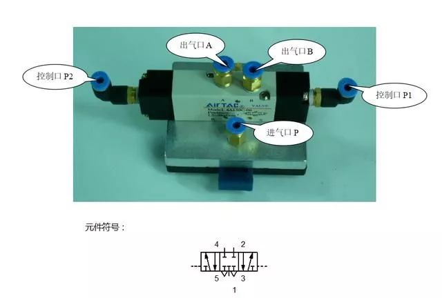
When the air inlet P is ventilated and the control ports P1 and P2 are airless, none of the air outlets A and B is output and the valve body is maintained at the neutral position. When the control port P1 is ventilated, the gas outlet B has a gas output. On the other hand, when the control port P2 is ventilated, the gas outlet A has a gas output.
Two-position three-way roller lever type directional valve
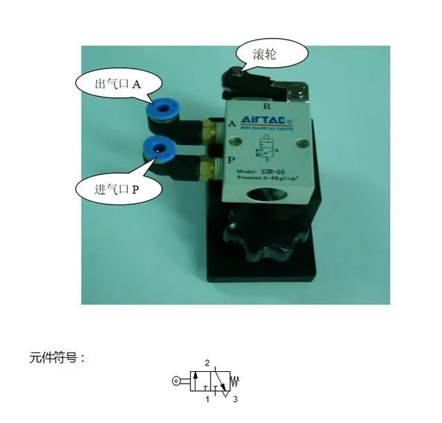
When the air inlet P is ventilated and the roller is pressed by the cylinder probe, the air outlet A has a gas output. Otherwise, A mouth is no gas output. According to the direction of the roller, the valve is divided into two pairs, ie, one pair, for detecting the position of the cylinder.
Two-position three-way roller lever through valve
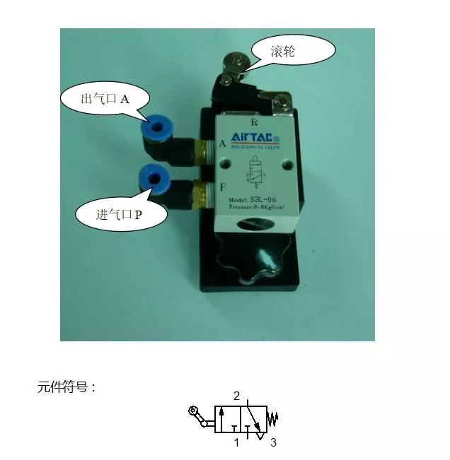
When the air inlet P is ventilated and the roller is pressed by the cylinder probe, the air outlet A has a gas output. Otherwise, A mouth is no gas output. According to the direction of the roller, the valve is divided into two pairs, ie, one pair, for detecting the position of the cylinder. When the cylinder probe is in the process of retracting, the roller part of the valve has the function of giving way automatically, which avoids the mutual rubbing between the probe and the roller, thus greatly reducing the phenomenon that the entire circuit can not work. This is commonly known as " Idler".
Quick exhaust valve
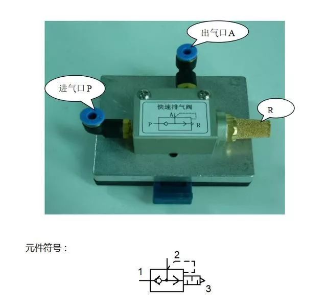
When the air inlet P is ventilated, the air outlet A has a gas output; when the air inlet P is airless, the air of the air outlet A is rapidly discharged into the atmosphere through the silencer of the R port.
Or valve (shuttle valve)
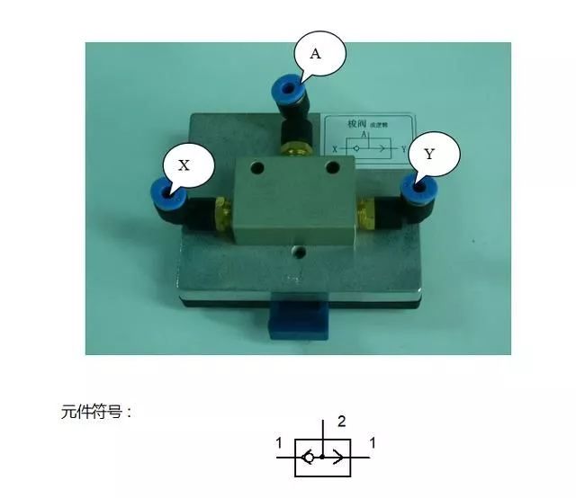
When X, Y mouth has any mouth ventilation, A mouth has gas output to achieve or logic.
With valve (double pressure valve)
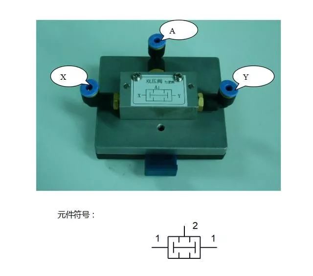
When both X and Y ports are vented, the A port has gas output to achieve the logic.
Optical Line Terminal (OLT)
Poe Switches,18Port Poe Switches,Promotional Industrial Switch,Ethernet Poe Industrial Switch
Shenzhen Scodeno Technology Co.,Ltd , https://www.scodenonet.com