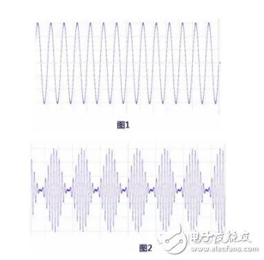
In the early days of radio development, most of the test engineers faced were continuous wave, amplitude modulation, frequency modulation, phase modulation, or pulse signals. These signals were regularly followed. For example, the power measurement of a continuous wave (Figure 1) frequency modulation or phase modulation signal is very simple, only the average power needs to be measured; the power of the amplitude modulation signal (Figure 2) is related to its modulation depth, and the characteristics of the pulse signal are Pulse width and duty cycle are expressed. For these analog or analog modulation signals, the RF power measurement is basically about the average power and the peak power.
Now, especially after the 1990s, digital communications began to develop rapidly, and the focus of RF power measurement began to change. Because the envelope of a digitally modulated signal (see Figure 3) has no regularity, its maximum and minimum levels will change randomly, and the amount of change will be large. In order to describe the characteristics of such signals, some new description methods have been introduced, such as collar power, burst power, and channel power. Many traditional power meters have been unable to meet the digital signal power measurement requirements, and part of the task of power measurement has begun to be completed by the spectrum analyzer.

Below we introduce several common RF power measurement methods, before we need to clear one thing - in the frequency domain test measurement, why are you accustomed to power to describe the signal strength, rather than as commonly used in time domain test measurements Voltage and current? That is because in the RF circuit, because of the presence of standing waves on the transmission line, the voltage and current lose their uniqueness. Therefore, the size of the RF signal is generally expressed in terms of power, and internationally used power units are W, mW, and dBm.
Both the spectrum analyzer and the power meter can measure RF power. The power meter is divided into two types: absorption power meter and pass power meter.
The same is the power measurement. Different test instruments and test methods focus on different points.
RF power measurement method:
· Spectrum Analyzer Measurements
Absorption power measurement
· Pass-through power measurement
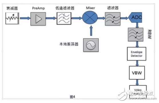
1, spectrum analyzer measurementSpectrum analyzer (hereinafter referred to as spectrum analyzer) is a basic frequency domain test and measurement instrument. Figure 4 shows the basic operating principle of the digital IF spectrum analyzer. The measured signal passes through the low-pass filter and enters the mixer, and is mixed with the local oscillator signal that enters the mixer at the same time. Since the mixer is a non-linear device, an intermodulation signal is generated. The signal falling into the filter passes through the ADC, and then enters an IF filter, an envelope detector, a video filter, a video detector, and finally the track is displayed on the screen. on.
When measuring RF power parameters, the spectrum analyzer has the following features:
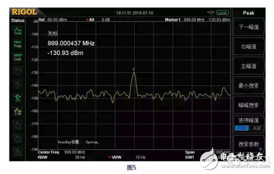
1) The spectrum analyzer can measure very small amplitude RF signals, which depends on a key indicator of the spectrum analyzer - the Displayed Average Noise Level (DANL), the Chinese "display average noise level". For example, the RIGOL DSA875 can reach this target - 161dBm/Hz, Fig. 5 is the signal result that DSA875 measures a frequency 999MHz, power -130dBm, the signal is clear and visible, this is beyond the reach of any power meter.
2) The spectrum analyzer has a very large amplitude measurement range, from DANL to safe input levels +20 dBm or even +30 dBm, with a dynamic range of up to 190 dB! At present, the maximum dynamic range of power meters on the market is basically within 100 dB, such as:
A company in Germany NRP8S: –70 dBm to +23 dBm
US company U2041XA: –70 dBm to +26 dBm
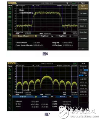
3) The spectrum analyzer can measure the frequency components of the signal and can perform narrowband measurements. For example, RIGOL's DSA875 has advanced measurement capabilities such as channel power and collar power, as shown in Figure 6 and Figure 7.
4) The spectrum analyzer can measure multiple carrier frequency signals at the same time and observe the distribution of the signal spectrum analyzer.
Absorption power measurementAbsorption power meter is commonly used microwave and RF power measurement equipment, its working principle shown in Figure 8 (diode detector power meter) shows. The measured signal first enters the power meter. The power meter circuit can be composed of thermistors, thermocouples, or diode detectors. The power meter is composed of three measurement channels and measures the signals of different power levels. After digital processing The power value is displayed to the power meter host or computer software, and now more and more display parts are implemented using software (Figure 9).
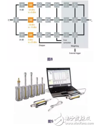
Absorption power meter has the following characteristics:
1) In common microwave and RF power measurement instruments, the absorption power meter's amplitude measurement accuracy is the highest;
2) The dynamic range will generally not exceed 100 dB;
3) Can not measure high power, usually the upper limit of the measurement is about +30 dBm (1 W), if you need to expand the measurement range, you need an external attenuator;
4) Measure the average power, peak power, burst power, pulse width, rise/fall time of various modulation signals;
5) The frequency components of the signal cannot be measured like a spectrum analyzer;
6) Cannot measure VSWR.
In view of these characteristics of the absorptive power meter, it is used as a laboratory calibration device and is used for the calibration of a signal source and a spectrum analyzer.
3, through the measurementPass-through power measurement is an extended application of the absorptive power measurement method, which solves the limitations of the absorptive power meter for measuring high power and VSWR. The greatest significance of the pass-through power measurement is the ability to measure the matching of the amplifier or transmitter to the load in a high-power state. When it comes to passable power meters, many people think of a product, the Bird 43 (Figure 10). It was invented by Bird in 1952 and is still in production and application.
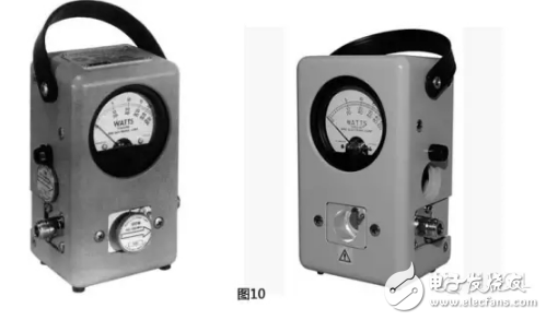
The core device of the pass power meter is a directional coupler, and the VSWR is calculated by measuring the forward power and the reflected power through the power meter. This measurement method has the following characteristics:
1) Pass-through power meter with high power measurement capability;
2) Cannot measure power with very small amplitude;
3) Pass-through power meters are limited by the bandwidth of the directional coupler, and the measurement bandwidth is much smaller than the spectrum analyzer and the absorptive power meter;
4) Through the power meter can measure the high power match between transmitter and load (antenna).
Through the introduction of this article, we can see that in the RF power measurement, the spectrum analyzer has inherent advantages in flexibility and application range, the absorption power meter has the highest precision, and the pass-through power meter is more biased towards the measurement of high power signals.
Wire Harness
Feyvan electronics offers a wide variety of cable assemblies including Servo Motor, Sensor, Automotive, Medical and other custom wire harness to help you prepare for installation. Whether you need cables, connectors, electrical components, tapes or heat shrink tubes, we have the products for you.
Our cable parts and accessories offer safe and efficient ways to get the job well done, all of which are RoHS, UL and CSA compliant. More than 10 years experiences of professional engineers ensure that your custom cables, assemblies, connectors and harnesses are perfectly suited to meet your exact requirements.
Wire Harness,Cable Assembly,Cable Harness,Wire Assembly
Feyvan Electronics Technology Co., Ltd. , https://www.fv-cable-assembly.com