As we all know, stepper motor drive method has an entire step, half step, subdivision drive. The three are both distinct and related. At present, many drives on the market support subdivision driving methods.
Everyone knows that a stepping motor is a control motor that converts an electrical pulse signal into a mechanical angular displacement and is often used as an actuator in a digital control system. When the step driver receives a pulse signal, it drives the stepper motor to rotate in a set direction by a fixed angle (this angle is called the pitch angle).
Under normal motion conditions, it has a fixed number of steps per revolution; when performing continuous stepping motions, its rotational speed maintains a strict correspondence with the frequency of input pulses, and is not affected by voltage fluctuations and load changes. This article Xiaobian will lead you to understand in detail the stepper motor full-step drive, half-step drive, subdivision drive working principle and advantages and disadvantages.
Stepper motor driveThe following figure shows the internal stator of the two-phase stepping motor. In order to make the rotor of the motor rotate continuously and smoothly, the stator must generate a continuous and average magnetic field. Because from a macroscopic point of view, the motor rotor always follows the direction of the magnetic field synthesized by the stator of the motor. If the magnetic field that the stator synthesizes changes too fast, the rotor can't follow, then the stepping motor will appear out of step.
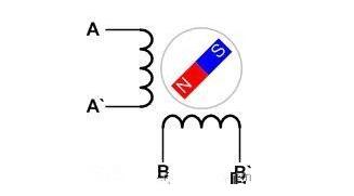
Since the motor rotor follows the motor stator magnetic field rotation, the stator stator magnetic field strength and direction are determined by the stator synthesis current and are proportional. That is, as long as the stator current of the motor is controlled, the purpose of driving the motor can be achieved. The following figure shows the current synthesis of a two-phase stepper motor. Among them, Ia is generated by AA` phase, Ib is generated by BB` phase, and the current I produced by the two of them is the composite current of the stator of the motor. It can represent the magnitude and direction of the magnetic field generated by the motor stator.
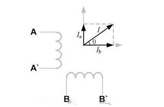
Based on the background description of the above stepper motor, the three steps of stepping motor's full-step, half-step, and subdivision are all the same, except that the current divides the thickness of a circle (360°) into different degrees.
1, full-step drive
For the full-step driving mode, the motor takes a whole step. For example, for a stepping motor with a step angle of 3.6°, the full-step driving is 3.6° per step.
The following figure shows the current sequence of the motor stator in the full-step drive mode:
From the above figure, we can see that there is only one phase energization at every moment in the full-step driving, so the driving circuit of this driving mode can be very simple, and the program code is also relatively easy to implement. From the above figure, the phase sequence of the motor step-by-step driving can be obtained as follows:
BB'→A'A→B'B→AA'→BB'
The following figure shows the current vector segmentation diagram of this driving method:
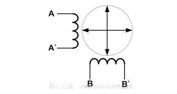
It can be seen that the current vector of the full-step driving mode divides a circle into four equal parts.
The following figure is the current I vs T graph of phase A and phase B of the full-step driving method:
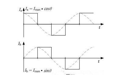
to sum up:
It can be seen that the disadvantage of the full-step drive: the sine wave traced out is rough. Use this way to drive the stepper motor. At low speed, the motor will shake and the noise will be large. However, the advantages of this type of drive: whether it is relatively simple in hardware or software, the drive manufacturing costs are easily controlled.
2, half-step drive
For a half-step drive, the motor takes one and a half steps. For example, for a stepper motor with a step angle of 3.6°, the half-step drive takes 1.8° (3.6°/2) per step.
The following figure shows the current sequence of the motor stator in the half-step drive mode:
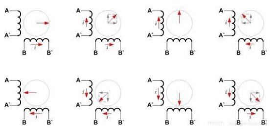
From the above figure, it can be seen that the half-step driving method is more complicated than the full-step driving method. At the same time, both phases may need to be energized. If the torque required to rotate the motor is stable, it needs to be energized when both are powered at the same time. The current should be sin (45°) of the single-phase energizing current, ie √2/2. Of course, a current equal to the single-phase current can be directly passed. As a result, the torque during the rotation of the motor is not constant, but the advantage thereof is the simplification of the drive circuit or software programming.
The following is the driving phase sequence of this driving mode:
BB'→BB' A'A→A'A→B'B A'A→ B'B→B'B AA'→AA'→ AA' BB'
If you need to reverse, simply press the reverse of the above phase sequence.
When the motor is energized in the above phase sequence, the resulting current vector can divide a circle into 8 parts, as shown in the following figure:
The half-step drive on the one hand doubles the stepping resolution of the motor and the motor runs more smoothly.
In contrast, the two-phase current diagram in the half-step drive mode is shown in the following figure:
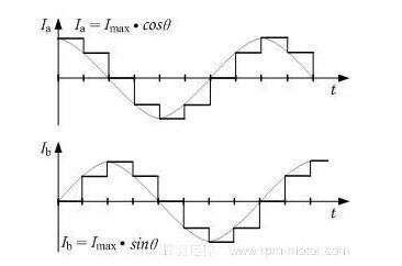
to sum up:
From the above figure, the advantage of the half-step driving method is that the sine wave described has been improved compared to the full-step driving method, and the accuracy has been improved. The advantage of this is that without changing the motor, the stepping angle resolution of the motor is doubled and the motor runs relatively quietly.
3, subdivision drive
As shown below, you can see some rules:
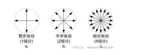
Looking at the picture above, the current vector segmentation circle is more and more dense, as shown in c above. This is a segmentation diagram of 4 subdivided driving. From the macroscopic point of view, it can be imagined that the angle at which the motor rotor takes one step will decrease with the increase in the number of subdivisions, and the motor rotation will become more and more stable and quiet. In a sense, full-step and half-step drives are also driven by subdivision, and their relationship is like the relationship between squares and rectangles.
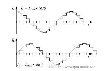
The above figure shows the two-phase current diagram of the 4 subdivided driving method. It can be seen from the figure that the current curve of each phase is more delicate than the current curve of the half-step driving.
Current subdivision is one of the methods of subdivided driving. The constant current is usually driven by a chopper, and the given current is a sine wave distribution. The other is voltage subdivision. This method is a coil of a voltage-driven motor that is smaller than a sinusoidal wave and can realize subdivided driving of the motor without feedback. However, because of the back-EMF of the motor, the sinusoidal voltage cannot be driven. A sine wave current is generated, the effect is not subdivided by the current, but its drive circuit is relatively simple.
to sum up:
Subdivision can improve the motor's step angle resolution. However, this is not the original intention of the subdivision drive, but it is to slow down the vibration and noise of the stepper motor operation process and make the motor torque output more stable. This is a bit like the relationship between the optical zoom and digital zoom of a digital camera. It is better to increase the resolution of the stepping system depending on the motor itself and the mechanical structure.
In engineering applications, the number of subdivisions of the motor may be different. At low speeds, the number of subdivisions may be increased, and as the speed increases, subdivisions are reduced.
The KSPOWER brand 5W~18W DC adapters is one black or white color constant voltage mode, accepts universal input 100-240V AC voltage and provides the complete external power supply solutions covering the single output voltage ranging from 5Volt to 36Volt and the output current ranging from 100ma to 3000ma. The switching power adaptor follows high quality level VI energy efficiency and meet IEC/EN/UL 62368-1 and 61558 safety standards, with UL/cUL CE FCC KC KCC TUV GS RCM CCC SAA C-Tick UKCA RoHS CB PSE PSB safety certificates export for global countries. The global power supply is Class I and Class II power designed with the AC outlet of IEC320-C14, IEC320-C6, IEC320-C8 and offers 3 years after-sale customer service. The external laptop adapter accepts various dc connector size for various audio/video and I.T.E applications and protections for short circuit, over load, over voltage and over temperature with green indication light for power on.
5W~18W DC Adapters
Shenzhenshi Zhenhuan Electronic Co., Ltd , https://www.szzhpower.com