Nowadays, with the increasing maturity of machine identification technology, machine identification can be seen everywhere in our daily life. Everyone has common two-dimensional code recognition, fingerprint recognition, license plate recognition, etc. These technologies are quite mature. There are also today's more unmanned systems. There are many machine identification technologies in unmanned systems, including identification of people or moving objects, signpost recognition, and distance estimation. In various identification systems, the identification of numbers is indispensable. The numbers are everywhere in our human world.
At present, the methods for achieving digital identification are roughly divided into the following four types:
1) Use software programming to implement on traditional personal PCs;
2) Use a general-purpose MCU microprocessor (51 microcontrollers, ARM, etc.) for implementation;
3) Use a general-purpose DSP as a system processor for implementation;
4) Use a dedicated DSP as the core of the operation;
In addition to the above four methods, FPGAs have the advantage of being able to run in parallel with their unique hardware, breaking the traditional processor sequential execution pattern, allowing multiple operations to be completed in parallel in a single clock cycle, compared to DSP processing speeds. The processing capability has been greatly improved. At the same time as it has the advantages of low cost, high degree of integration, ease of post-maintenance, and upgrade, the speed of the system can meet the requirements of real-time image processing. Therefore, this design decided to use FPGA as the hardware platform. , Design and implementation of an FPGA-based digital identification system.
2 FPGA-based digital identification methodIn general, algorithms used for digital recognition of printed objects include: template-based identification methods, BP neural network-based identification methods, and digital feature-based identification methods. These kinds of algorithms are discussed and compared below.
1" template matching method
Template matching method is a digital identification algorithm applied earlier. The key of this algorithm is to build a template for all the numbers to be recognized. After comparing the numbers in the image with all the digital templates one by one, the image is calculated. The similarity between the numbers and each template is identified based on the calculated similarity results. The template with the highest degree of similarity is the result we want to identify. The template matching method has a high degree of standardization for the size, structure and shape of numbers, and the degree of digitization has a direct impact on the accuracy of recognition. The principle of the algorithm is relatively simple, but the computational complexity is too large and it is not conducive to the realization of FPGA.
2 "neural network identification algorithm
The neural network identification method is an algorithm that simulates the characteristics of animal neural networks and distributes information in parallel. The neural network recognition algorithm has certain anti-jamming capability, but in order to ensure the recognition accuracy, the algorithm needs to be responsible and a large number of calculations to train the neural network, and overly complex calculations are not conducive to FPGA implementation of the algorithm.
3" Digital Feature Recognition Algorithm
The core of the recognition algorithm based on digital features is to analyze and count the geometrical features such as the shape and structure of numbers, and to recognize the digital features to achieve the recognition of the figures in the image.
3 Digital recognition based on digital feature algorithm
We use the digital feature-based algorithm for digital recognition. The image acquisition module collects the image and performs the graying and binarization. Then the digital feature extraction and statistics are performed to complete the digital recognition and finally display to the digital tube. Complete conversion of image information to digital information.
![1 Background knowledge Nowadays, with the increasing maturity of machine identification technology, machine identification is also seen everywhere in our daily life. Everyone has common two-dimensional code recognition, fingerprint recognition, license plate recognition, etc. These technologies are quite mature. There are also today's more unmanned systems. There are many machine identification technologies in unmanned systems, including identification of people or moving objects, signpost recognition, and distance estimation. In various identification systems, the identification of numbers is indispensable. The numbers are everywhere in our human world. At present, the methods for achieving digital identification are broadly classified into the following four types: 1) Use software programming to implement on a conventional personal PC; 2) Use a general-purpose MCU microprocessor (for example, 51 SCM, ARM, etc.) to implement it; 3) Use The general DSP is implemented as a system processor; 4) The dedicated DSP is used as the operation core; In addition to the above four methods, the advantages of the FPGA, which can run in parallel with its unique hardware, break the traditional processor sequential execution mode. Completing multiple operations in parallel in a single clock cycle significantly improves the processing speed and processing power of the DSP compared to the DSP. The system runs at the same time as the low cost, high degree of integration, ease of post-maintenance, and upgrade. Speed ​​can meet the needs of real-time image processing, so the design decided to use FPGA as a hardware platform, design and implementation of a digital recognition system based on FPGA. 2 Digital recognition method based on FPGA Generally, the algorithms used for digital recognition of printed objects are: recognition method based on template matching, identification method based on BP neural network, and identification method based on digital features. These kinds of algorithms are discussed and compared below. 1) Template Matching Template Matching is a digital identification algorithm that was applied earlier. The key to this algorithm is to build a template for all the numbers to be identified. Then the numbers in the image are compared with all the digital templates one by one. Calculate the similarity between the numbers in the image and each template, and identify them based on the calculated similarity results. The template with the highest degree of similarity is the result we want to identify. The template matching method has a high degree of standardization for the size, structure and shape of numbers, and the degree of digitization has a direct impact on the accuracy of recognition. The algorithm principle is relatively simple, but the computational complexity is too large and it is not conducive to FPGA implementation. 2) Neural Network Recognition Algorithm The neural network identification method is an algorithm that mimics the characteristics of animal neural networks and distributes information in parallel. Neural network recognition algorithm has certain anti-interference ability, but in order to ensure the accuracy of recognition, the algorithm needs to be responsible and a large number of calculations to train the neural network, and overly complex calculations are not conducive to FPGA implementation of the algorithm. 3 “Digital Feature Recognition Algorithm†The core of the recognition algorithm based on digital features is to analyze and count the geometric features such as the shape and structure of numbers, and to identify the digital features through recognition of digital features. 3 Digital recognition based on digital feature algorithm We use digital feature-based algorithms for digital recognition. The image acquisition module collects the image, performs graying, and binarizes it, and then performs digital feature extraction and statistics to complete the digital The identification is finally displayed on the digital tube and the conversion of image information to digital information is completed. 1 Figure 2 7-8 Digital character marking 2 Figure 3 5 Digital character information extraction based on the print body, as shown in Figure 1, Figure 2, Figure 3, Figure 3 Figure 5, the red box is the number 5 Horizontal and vertical upper and lower left and right borders. X1 is a horizontal line at 2/5 in the vertical direction, x2 is a horizontal line at 2/3 in the vertical direction, and y is a water line at 1/2 in the horizontal direction. We use this feature to count the intersection of x1, x2, y and the number 5. The cross-statistical method is used to distinguish the characteristics of the 0-9 digits as shown in Table 1: Table 1 0-9 Numeric Signature Table 3 Since the 2, 3, and 5 digital signature tables cannot be distinguished, we continue to increase the numeric characteristics to distinguish 2 ,3,5. As shown in Table 2: Table 2, 2, 3, 5 Digital Signature Statistics 3 This completely distinguishes the numbers 0-9 by means of numerical statistics. Then use the FPGA system to build a real-time digital identification system. 4 FPGA-based digital recognition implementation 4 Figure 4 Based on ov5640 FPGA real-time digital identification system shown in Figure 4, we use ov5640 500W pixel camera image acquisition, the collected color RGB image first stored in SDRAM, and then by the TFT display After the control unit reads out the image data and reads out the RGB image data, we first perform an RGB to Ycbcr algorithm operation, and then perform threshold segmentation on the grayscale image to form a binary image. Digital recognition of binary digital images is finally displayed on the digital tube. FPGA part source code: //-------------------------------------------- ---------------------------- // VGA display //---------------- -------------------------------------------------- -------- always @(posedge TFT_VCLK or negedge rst_n) begin if(!rst_n) TFT_RGB <<=16'b0; else if(hcount == 400 || vcount == 192 || vcount == 320) TFT_RGB "= 16'hff00; else TFT_RGB "={o_y_8b[7:3],o_y_8b[7:2],o_y_8b[7:3]}; end //------------- ------------------------------------------------ // Digital tube display //--------------------------------------------- ---------------- always @(posedge TFT_VCLK or negedge rst_n) begin if(!rst_n) disp_data <<=32'h0; else if((!TFT_VS_r0) && TFT_VS_r1) case( {x1_l, x1_r, x2_l, x2_r, y, x1, x2}) 16'b1111_0010_0010_0010: disp_data "= {28'b0,4'h0}; //0 16'b1010_0001_0001_0001: disp_data "= {28'b0,4'h1}; //1 16'b0110_0011_0001_0001: disp_data "= {28'b0,4'h2}; //2 16'b0101_0011_0001_0001: disp_data "= {28' B0,4'h3}; //3 16'b1110_0010_0010_0001: disp_data "= {28'b0,4'h4}; //4 16'b1001_0011_0001_0001: disp_data "= {28'b0,4'h5}; //5 16'b1011_0011_0001_0010: disp_data "= {28'b0,4'h6}; //6 16'b0110_0010_0001_0001: disp_data "= {28'b0,4'h7}; //7 16'b1111_0011_0010_0010: disp_data "= {28' B0,4'h8}; //8 16'b1101_0011_0010_0001: disp_data "= {28'b0,4'h9}; //9 default: disp_data "= 32'b0; endcase else disp_data "= disp_data; End Results display: Figure 5 Experimental original image Figure 6 Number 5 identification Figure 7 Number 7 Recognition result analysis: This experiment completed a single digit recognition of 0-9 digits. Identifying a plurality of digital, we want to split module, and then the identification number inside each module. We can add voice systems to broadcast the numbers we identify, and we have reached more humane and more practical development.](http://i.bosscdn.com/blog/o4/YB/AF/rQY62AVsrWAAB242ieDyI899.png)
Figure 2 7-8 Digital Feature Marking
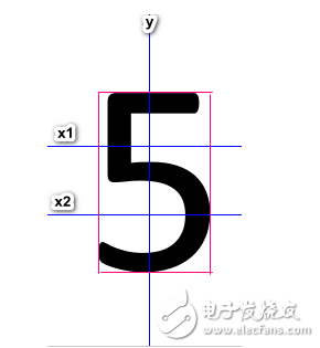
Figure 3 5 Digital Features
The extraction of digital feature information is based on a print body, as shown in FIG. 1, FIG. 2, and FIG. 3, and taking the number 5 of FIG. 3 as an example, the red frame is a horizontal and vertical left, right, and left boundary of the numeral 5. X1 is a horizontal line at 2/5 in the vertical direction, x2 is a horizontal line at 2/3 in the vertical direction, and y is a water line at 1/2 in the horizontal direction. We use this feature to count the intersection of x1, x2, y and the number 5.
The cross-statistical method to distinguish 0-9 numbers is as follows:
Table 1 0-9 Digital Feature Statistics
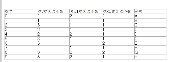
Since the 2,3,5 digital feature statistics are indistinguishable, we continue to increase the digital features to distinguish 2,3,5. As shown in Table 2:
Table 2 2,3,5 Digital Feature Statistics

This completely discriminates the numbers 0-9 by means of numerical statistics. Then use the FPGA system to build a real-time digital identification system.
4 FPGA-based digital recognition implementation
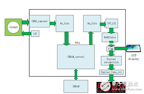
Figure 4 Based on ov5640 FPGA real-time digital identification system
As shown in Figure 4, we use ov5640 500W pixel camera to capture the image. The collected color RGB image is first stored in SDRAM, and then the TFT display control terminal reads out the image data. After reading the RGB image data, we first perform RGB conversion. The Ycbcr algorithm operates and then thresholds the grayscale image to form a binary image. Digital recognition of binary digital images is finally displayed on the digital tube.
FPGA part source code:
//------------------------------------------------ ------------------------
// VGA display
//------------------------------------------------ --------------------------
Always @(posedge TFT_VCLK or negedge rst_n) begin
If(!rst_n)
TFT_RGB "= 16'b0;
Else if(hcount == 400 || vcount == 192 || vcount == 320)
TFT_RGB "= 16'hff00;
Else
TFT_RGB <<= {o_y_8b[7:3],o_y_8b[7:2],o_y_8b[7:3]};
End
//------------------------------------------------ -------------
//digital tube display
//------------------------------------------------ -------------
Always @(posedge TFT_VCLK or negedge rst_n) begin
If(!rst_n)
Disp_data <<= 32'h0;
Else if((!TFT_VS_r0) && TFT_VS_r1)
Case({x1_l,x1_r,x2_l,x2_r,y,x1,x2})
16'b1111_0010_0010_0010: disp_data "= {28'b0,4'h0}; //0
16'b1010_0001_0001_0001: disp_data "= {28'b0,4'h1}; //1
16'b0110_0011_0001_0001: disp_data "= {28'b0,4'h2}; //2
16'b0101_0011_0001_0001: disp_data "= {28'b0,4'h3}; //3
16'b1110_0010_0010_0001: disp_data "= {28'b0,4'h4}; //4
16'b1001_0011_0001_0001: disp_data "= {28'b0,4'h5}; //5
16'b1011_0011_0001_0010: disp_data "= {28'b0,4'h6}; //6
16'b0110_0010_0001_0001: disp_data "= {28'b0,4'h7}; //7
16'b1111_0011_0010_0010: disp_data "= {28'b0,4'h8}; //8
16'b1101_0011_0010_0001: disp_data "= {28'b0,4'h9}; //9
Default: disp_data <<= 32'b0;
Endcase
Else
Disp_data "= disp_data;
End
Results show:
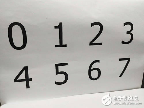
Figure 5 Experimental artwork
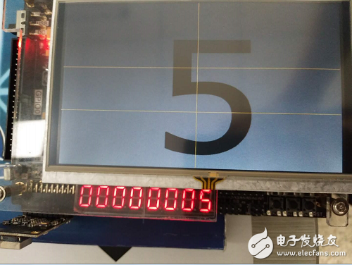
Figure 6 Number 5 Identification
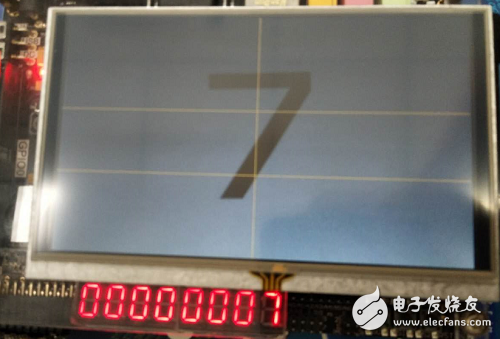
Figure 7 Number 7 Identification
Result analysis:
This experiment completed a single digit recognition of 0-9 digits. For the identification of multiple digits, we need to perform module segmentation and then identify the digits in each module. We can add voice systems to broadcast the numbers we identify, and we have reached more humane and more practical development.
Strain/flex Reliefs And Grommets
the power Connectors we provide overmolding solutions and modular tooling.
We also offer to the OEM and distributor users a diversified line of strain / flex reliefs and grommets, such as Solid, Solid-Rib, Uniflex, Multiflex, in standard off the shelf or custom designs.
Overmolding the power connectors offers significant opportunities for cable improvements with higher pull strength not available with conventional backshells. Our technical staff is ready to help you from design and prototyping to small production run, assistance, and training.
Our team is ready to help with any of the following power connectors projects: overmolding mini fit jr. and mini-fit sr. connectors, , overmolded cables with micro fit terminations, sabre molded cable asemblies, amp duac overmolded power connectors, mate-n-lock power cables, power connector overmolding services, power connector molding, design and prototype of power cables across the board, small run molded power connecotrs , molded cable manufacturing, overmolding connectors for any power applications
Strain Reliefs And Grommets,Flex Reliefs And Grommets,Cable Strain Reliefs,Cable Flex Reliefs,Cable Grommets,Molded Strain Relief
ETOP WIREHARNESS LIMITED , https://www.wireharnessetop.com