This article describes an advanced method for over-current and short-circuit protection of full SiC modules using current sense terminals. At the same time, the results of testing with newly developed drivers are given. Newly developed drivers integrate features such as over-current protection, soft shutdown, and active clamping.
1 Introduction
Full SiC module FMF800DX-24A (1200V/800A) is mainly used in high frequency (switching frequency 30kHz~100kHz), high efficiency or high power density occasions.
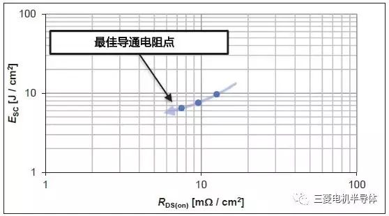
Compared to silicon devices, full SiC modules can significantly reduce switching losses. On the other hand, the on-state losses are optimized while ensuring short-circuit capability. The on-resistance of a SiC MOSFET chip is inversely proportional to its short-circuit tolerance. Figure 1 shows the tradeoff between the on-resistance (RDS(on)) of the SiC MOSFET die and its short-circuit tolerance (ESC).

Fig.1 The trade-off curve between on-resistance and short-circuit tolerance of SiC MOSFET chip
Because the SiC MOSFET chip can withstand a limited short-circuit tolerance (us), it is a good choice to use a separate current detection terminal in order to reduce the response time of the short circuit and reduce the short circuit energy. In this way, the on-resistance of the SiC MOSFET chip can be designed to be relatively small. At the same time, the overcurrent protection threshold can be arbitrarily adjusted and can be easily detected, and suitable measures can be used in the drive circuit for short-circuit shutdown. As a result, both the short-circuit current value and the short-circuit energy can be significantly reduced.
2. Full SiC MOSFET short-circuit tolerance
The FMF800DX-24A internally uses eight 100A SiC MOSFETs in parallel. The gate threshold voltage VGS(th) is typically 1V. For the short-circuit tolerance, the distribution of VGS(th) must be considered. Figure 2 shows the short-circuit resistance of the FMF800DX-24A as a function of VGS(th). The actual maximum withstand short-circuit time (Figure 2 solid line) is 3~4us, and the maximum short-circuit energy is 18.4J. The maximum tolerable short circuit time defined in the FMF800DX-24A datasheet is tsc(max)=2us, which cannot be exceeded during use. When a short circuit occurs, it is difficult to ensure that the FMF800DX-24A is turned off in such a short period of time if the traditional method of desaturation voltage detection is used. Therefore, it is recommended to use the current detection terminals of the module to design more advanced short-circuit protection measures.
Fig. 2 The relationship between the short-circuit tolerance and VGS(th) of FMF800DX-24A (VDD=850V, Tj=150°C, VGS=+15V)
3. Advanced over-current and short-circuit detection methods
The 100A/200V SiC MOSFET chip used in the FMF800DX-24A has an isolated area on the metallization source and is connected to the current sense terminal. In this way, the current at the current detection terminal is proportional to the main circuit current. Figure 3 shows a MOSFET chip image and its simplified equivalent circuit. (Equivalent circuit diagram on the left and photo of the chip on the right.)
Figure 3 SiC MOSFET chip with integrated current sense terminals
The voltage VS above the sense resistor RS shown in FIG. 3 can be used for overcurrent detection. The ratio of the current flowing through the sense resistor to the main circuit is 1: 61500. The relationship between the voltage VS above the sense resistor RS and the junction temperature Tj is shown in FIG. After taking into account the current relationship and temperature effects, an appropriate sense resistor RS can be selected to set the desired overcurrent protection threshold.
Figure 4 Relationship between drain current and sense voltage
4. Implementation of FMF800DX-24A Driver Protection Function
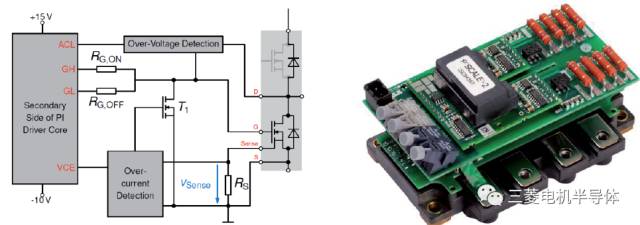
The advanced protection method using current detection and used in the FMF800DX-24A is achieved through the reference design RDHP-1417 (which uses the driver core 2SC0435T) [4][5] and includes overvoltage protection and overcurrent protection. The internal integrated active clamp circuit achieves overvoltage protection, while the overcurrent protection is achieved by setting the detection voltage to trigger the soft turn-off function of the gate drive. The equivalent schematic of the driver used is shown in Figure 5.

Figure 5 Photo of the driver (right) and its equivalent circuit block diagram (left)
5. Overvoltage protection
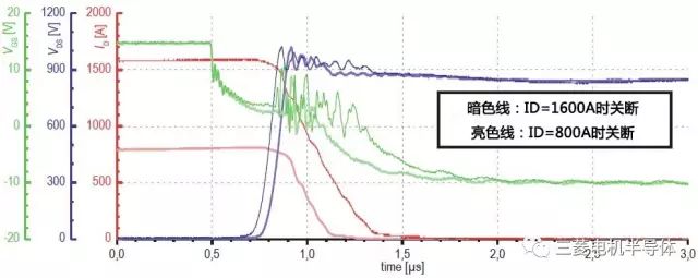
Turning off the device at high currents with large di/dt will cause it to withstand excessive voltage spikes. If the device operates below the overcurrent protection threshold, it is recommended that the driver add additional measures to suppress the shutdown voltage spike to ensure that it is less than 1200V. A good measure is to use an active clamp circuit with integrated dv/dt feedback (the module will not be actively shut down and no fault signal will be generated).
Figure 6 shows the shutdown waveforms of the FMF800DX-24A at 800A and 1600A. It can be seen from the waveform that overvoltage protection safely limits the VDS voltage below 1200V.

Figure 6 Turn-off waveform of the FMF800DX-24A at rated current and 2 times rated current (VDD=850V, Tj=25°C)
6. Overcurrent protection
The overcurrent protection threshold of the evaluated driver is 2000A (2.5 times rated current). When the current exceeds this value, the driver will actively perform soft turn-off and feedback the fault signal to the controller. Figure 7 shows the waveform when the shutdown current is slightly less than the over-current protection threshold and is compared to the soft-off waveform during over-current. It can be seen from the above that there is no obvious overvoltage on the power module during soft turn-off.
Figure 7 Over-Current Protection and 2.5x Rated Current Shutdown Waveform (VDD=850V, Tj=25°C)
7. Short circuit protection
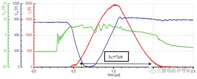
A short-circuit test was performed under the conditions of bus voltage VDD = 850V and short circuit loop inductance LSC = 170nH to verify the short-circuit protection function of the driver. Figure 8 shows the corresponding test results. When the current is approximately 2000A, the overcurrent is detected and the soft turn-off is immediately performed. Short circuit time is about 1us, and short circuit energy is 0.65J. Both of these indicators are significantly lower than the upper limit of the module and less than the design limit of the device. By using the soft-off function, the voltage spike at short circuit can be well controlled below 1000V.

Figure 8 FMF800DX-24A short circuit test waveform (VDD = 850V, Tj = 25 °C)
8. Conclusion
Mitsubishi Electric provides a reliable new device solution for efficient, ultra-compact converters (hundreds of kW): the FMF800DX-24A. For this all-SiC device, PI has developed a corresponding driver reference design (RDHP-1417). By using the mirror current terminal of the module, overcurrent protection can be effectively performed in the event of a short circuit or the like. At the same time, the driver integrates an active voltage clamp and a soft-off function to effectively suppress voltage spikes at high-current shutdown.
Marine Control Cable,Cwb Marine Control Cable,Ship Control Cable,Shield Marine Cable
Baosheng Science&Technology Innovation Co.,Ltd , https://www.bscables.com