introduction:
Hall sensor is the world's third-largest sensor product, which is widely used in industrial, automotive, computer, mobile and emerging consumer electronics.
In the next few years, as more and more automotive electronics and industrial design companies move to China, Hall sensors' annual sales in the Chinese market will maintain a high growth rate of 20% to 30%.
At the same time, the related technologies of Hall sensors are still being improved, and programmable Hall sensors, intelligent Hall sensors and micro Hall sensors will have better market prospects.
What is the Hall effect?
The Hall effect is a kind of magnetoelectric effect. This phenomenon was discovered when Hall (AHHall, 1855-1938) studied the conductive mechanism of metal in 1879.
Later, it was found that semiconductors, conductive fluids, etc. also have this effect, and the Hall effect of semiconductors is much stronger than that of metals. When the current is perpendicular to the external magnetic field, the carriers are deflected, and the direction perpendicular to the current and the magnetic field produces a The electric field is added to generate a potential difference across the conductor. This phenomenon is the Hall effect, which is also called the Hall potential difference. The Hall effect should be judged using the left-hand rule.
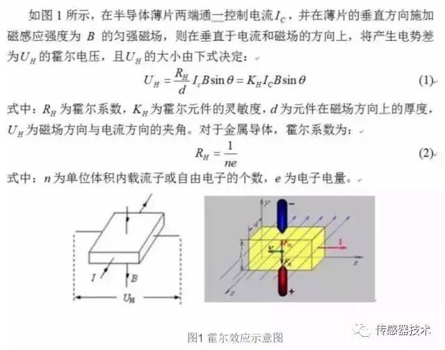
In equation (1): if the control current Ic is kept constant, under certain conditions, the magnitude of the magnetic induction can be calculated by measuring the Hall voltage, thereby establishing a relationship between the magnetic field and the voltage signal. According to this relationship, A semiconductor device, that is, a Hall element, for measuring a magnetic field has been developed.
The essence of the Hall effect is that when carriers in a solid material move in an applied magnetic field, the trajectory shifts due to the Lorentz force, and charge accumulation occurs on both sides of the material, forming a direction perpendicular to the current. The electric field eventually balances the Lorentz force of the carrier with the repulsion of the electric field, thereby establishing a stable potential difference, that is, the Hall voltage, on both sides.
The ratio of the orthogonal electric field and the product of the current intensity to the magnetic field strength is the Hall coefficient. The ratio of the parallel electric field to the current intensity is the resistivity. A large number of studies have revealed that not only negatively charged electrons but also positively charged holes are involved in the conductive process of materials.
What is a Hall sensor?
Hall sensor is a magnetic field sensor based on Hall effect, which is widely used in industrial automation technology, detection technology and information processing.
The Hall coefficient measured by the Hall effect experiment can determine important parameters such as conductivity type, carrier concentration, and carrier mobility of the semiconductor material.
Since the potential difference generated by the Hall element is small, the Hall element is usually integrated with an amplifier circuit, a temperature compensation circuit, and a regulated power supply circuit on a chip, which is called a Hall sensor. Hall sensors, also known as Hall ICs, have a small profile, as shown in the following figure:
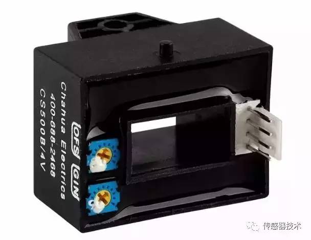
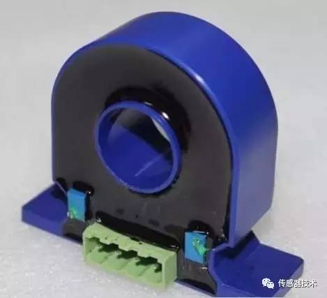
Hall sensor
Advantages and uses of Hall sensors
Many people know that the more automated the car, the more microelectronic circuits, the more afraid of electromagnetic interference. In the car, there are many lamps and electrical devices, especially the high-power headlamps, air-conditioner motors and wiper motors generate surge current when switching, causing arcing of mechanical switch contacts and generating large electromagnetic interference. signal.
These phenomena can be reduced by using a power Hall switching circuit. The Hall device is converted to an electrical signal output by detecting changes in the magnetic field and can be used to monitor and measure changes in the operating parameters of various components of the vehicle.
Such as position, displacement, angle, angular velocity, rotational speed, etc., and these variables can be transformed twice; pressure, mass, liquid level, flow rate, flow rate, etc. can be measured. The output of the Hall device is directly interfaced with the electronic control unit for automatic detection.
The current Hall devices can withstand certain vibrations, and can work in the range of minus 40 ° C to minus 150 ° C. All the seals are not polluted by water and oil, and can fully adapt to the harsh working environment of the car.
Hall sensors measure current and voltage in arbitrary waveforms such as DC, AC, pulse waveforms, and even transient peak measurements. The secondary current faithfully reflects the waveform of the primary current. Or ordinary transformers can not be compared with it, it is generally only suitable for measuring 50Hz sine wave
There is good electrical isolation between the primary side circuit and the secondary side circuit, and the isolation voltage can reach 9600Vrms;
High precision: accuracy is better than 1% in the working temperature zone. This precision is suitable for any waveform measurement; Hall switch device has no contact, no wear, clear output waveform, no jitter, no rebound, high position repeatability ( Up to μm level).
Wide bandwidth: The high-bandwidth current sensor rise time can be less than 1μs; however, the voltage sensor bandwidth is narrow, generally within 15kHz, and the 6400Vrms high-voltage voltage sensor has a rise time of about 500uS and a bandwidth of about 700Hz.
Wide measurement range: current measurement up to 50KA, voltage measurement up to 6400V.
The structure is firm, the volume is small, the weight is light, the service life is long, the installation is convenient, the power consumption is small, the frequency is high (up to 1 MHZ), the vibration is resistant, and the pollution or corrosion of dust, oil, water vapor and salt spray is not afraid.
The picture above shows a typical Hall sensor for positioning applications - two magnets on one wheel pass through a Hall effect sensor. The wheel in the illustration, with two equidistant magnets, the voltage across the sensor will peak twice in one cycle.
It is commonly used to measure the speed of wheels and shafts, such as at the ignition timing (timing) of an internal combustion engine or on a tachometer. It is used in brushless DC motors to detect the position of permanent magnets.
Hall sensors are widely used in frequency conversion speed control devices, inverter devices, UPS power supplies, communication power supplies, electric welding machines, electric locomotives, substations, CNC machine tools, electrolytic plating, computer monitoring, power grid monitoring, etc. Solar, wind and subway track signals, automotive electronics and other fields.
Main characteristic parameters of Hall sensor
As mentioned above, the Hall sensor is a magnetic field sensor fabricated according to the Hall effect. Its main characteristic parameters are as follows.
(1) Input resistance R
The DC resistance of the two excitation current terminals of the Hall sensor element is called an input resistance. Its value ranges from a few euros to a hundred euros, depending on the components of the different models.
As the temperature rises, the input resistance becomes smaller, which causes the input current to become larger, eventually causing the Hall sensor potential to change. In order to reduce this effect, it is preferable to use a constant current source as an excitation source.
(2) Output resistance R
The resistance between the potential outputs of the two Hall sensors is called the output resistance, and its digits are of the same order of magnitude as the input resistance. It also changes with temperature changes. Choosing the appropriate load resistor is easy to match to minimize the drift of the temperature-induced water potential.
(3) Maximum excitation current I---Hall sensor parameters
Since the potential of the Hall sensor increases with the increase of the excitation current, it is always desirable to select a larger excitation current of 1 M in the application but the excitation current is increased, the power consumption of the component is increased, and the temperature of the component is increased. As a result, the temperature drift of the Hall sensor's potential increases, so each of the models specifies a corresponding maximum excitation current, which ranges from a few milliamps to hundreds of milliamps.
(4) Sensitivity K
Sensitivity KH = EH / IB, its value is about 10MV (MA.T).
(5) Maximum magnetic induction BM---Hall sensor parameters
When the magnetic induction exceeds BM, the nonlinear error of the Hall sensor potential will increase significantly, and Tes(T) becomes several thousand Gauss (Gs) (1Gs = 104T).
(6) an equipotential potential
At the rated excitation current F, when the applied magnetic field is zero, it is an error due to the asymmetry of the geometry of the four dipoles.
(7) Hall sensor potential temperature coefficient
The value of 6M is generally zero. The open circuit voltage between the output terminals of the Hall sensor is called the unequal potential. When using the bridge method, the bridge method is used to compensate the unequal potential, which is caused by a certain magnetic induction intensity and excitation current. When the temperature changes by 1 degree Celsius, the percentage change of the Hall sensor potential is weakly the Hall sensor potential temperature coefficient, which is related to the material of the Hall sensor element.
Classification of Hall sensors
Hall sensors are classified into linear Hall sensors and switch Hall sensors.
1) The linear Hall sensor consists of a Hall element, a linear amplifier, and an emitter follower, which outputs an analog quantity.
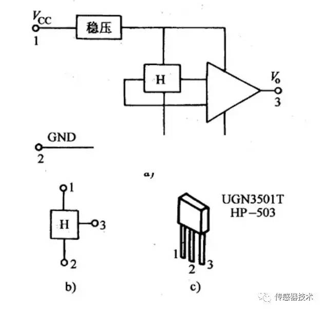
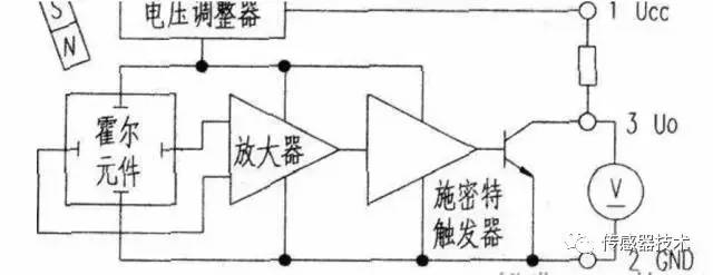
2) The switching Hall sensor consists of a voltage regulator, a Hall element, a differential amplifier, a Schmitt trigger and an output stage, which outputs a digital quantity.
According to the nature of the objects being detected, their applications can be divided into direct applications and indirect applications. The former is to directly detect the magnetic field or magnetic characteristics of the object to be detected, and the latter is to detect the artificial magnetic field set on the object to be inspected.
Hall sensor applications in various fields
According to the nature of the objects being detected, their applications can be divided into direct applications and indirect applications. The former directly detects the magnetic field or magnetic characteristics of the object to be inspected, and the latter detects the artificially set magnetic field on the object to be used, and uses this magnetic field as a carrier for the detected information, through which many non-electrical and non-magnetic materials are used. Physical quantity.
For example, force, moment, pressure, stress, position, displacement, velocity, acceleration, angle, angular velocity, number of revolutions, speed, and time when the working state changes, etc., are converted into electricity for detection and control.
(1) Linear Hall sensors are mainly used for the measurement of some physical quantities.
1. current sensor:
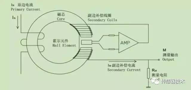
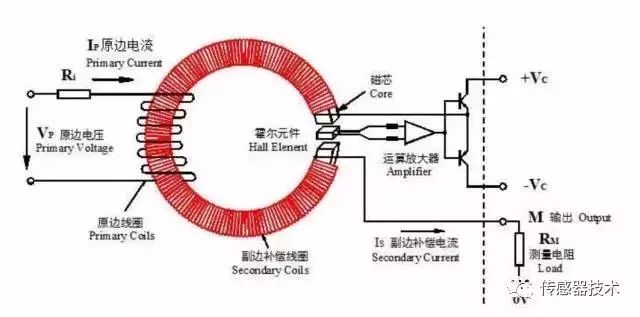
Since there is a magnetic field inside the energized solenoid, its magnitude is proportional to the current in the wire, so the Hall sensor can be used to measure the magnetic field to determine the current in the wire.
Using this principle, a Hall current sensor can be designed. The advantage is that it does not make electrical contact with the circuit under test, does not affect the circuit under test, does not consume the power of the power source under test, and is particularly suitable for high current sensing.
The Hall current sensor works as shown:
The standard toroidal core has a notch, the Hall sensor is inserted into the notch, the coil is wound around the ring, and when a current is generated through the coil, the Hall sensor has a signal output.
2. Displacement measurement:
as the picture shows:
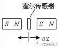
The two permanent magnets are placed opposite each other with the same polarity. The linear Hall sensor is placed in the middle, and the magnetic induction intensity is zero. This point can be used as the zero point of the displacement. When the Hall sensor is â–³Z displacement on the Z axis, the sensor has A voltage output whose voltage is proportional to the displacement distance.
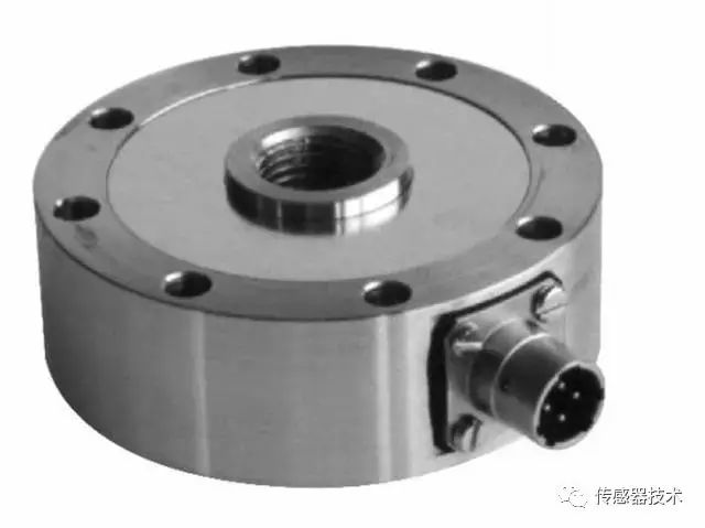
If the parameters such as tension and pressure are changed to the displacement distance, the tension and pressure can be measured. As shown in the figure below, the torque sensor is made according to this principle.
(2) Switching Hall sensors are mainly used for measuring the number of revolutions, speed, wind speed, flow rate, proximity switch, door closing informant, alarm, automatic control circuit, etc.
1. Measuring the speed or number of revolutions:
As shown below:
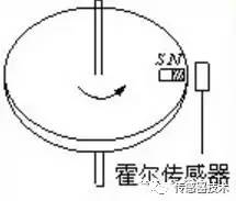
A magnetic steel is adhered to the edge of the disc of the non-magnetic material, the Hall sensor is placed near the edge of the disc, and the disc rotates once, and the Hall sensor outputs a pulse, so that the number of revolutions (counter) can be measured. By entering the frequency meter, the speed can be measured.
If the switch-type Hall sensor is regularly arranged on the track at a predetermined position, a pulse signal can be measured from the measuring circuit when a permanent magnet mounted on the moving vehicle passes through it. The speed of movement of the vehicle can be measured based on the distribution of the pulse signal.
2. Various practical circuits:
Switched Hall sensors are extremely versatile due to their small size, wide operating voltage range, reliable operation and low cost.
An example of the following is given:
Car door status display:
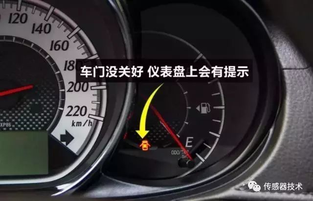
Now cars generally have this feature. Here, the Hall sensor is used. As long as a small permanent magnet is placed, it is easy to make an indicator that the door is closed. The configuration circuit is as follows:
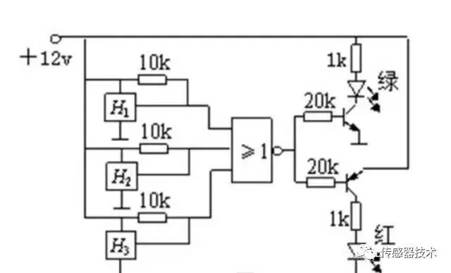
Three switch-type Hall sensors are respectively mounted on the four door frames of the car, and each piece of magnetic steel is fixed at the appropriate position of the door. When the door is open, the magnetic steel is away from the Hall switch, and the output end is at a high level. If one of the four doors is not closed, the NOR gate output is low, and the red light is on, indicating that there is still a door that is not closed. If all three doors are closed, the NOR gate output is high. The green light is on, indicating that the door is closed and the driver can drive safely.
Hall sensor outlook
Hall sensors have a double-digit growth rate in the Chinese market, and Hall sensors are widely used in our daily lives. For example, in a flip-top or slide-type mobile phone, the device for detecting the opening or sliding of the mobile phone cover is a Hall sensor; for example, on a computer keyboard, the scroll key for moving the cursor is composed of a Hall sensor. There are also Hall sensor applications in automotive gearboxes, electric windows and doors that require motors. We are dealing with Hall sensors in our daily lives.
The field of Hall sensor applications is different, so the requirements of each market are not the same. The main requirements of the mobile phone market for Hall sensors include size, power consumption and adjustable thresholds. In industrial and automotive applications, Hall sensors first meet the requirements of industrial or automotive certification for devices such as safety, stability and temperature range to the appropriate level.
With the continuous development of these terminal applications, Hall sensors are also miniaturized, highly integrated, highly sensitive, and temperature resistant.
Draw-out Type Low Voltage Switchgear Systems MNS
Draw-Out Type Low Voltage Switchgear Systems Mns,Draw-Out Type Low Voltage Switchgear Systems,Low Voltage Switchgear Systems,Lv Switchgear Systems
TRANCHART Electrical and Machinery Co.,LTD , https://www.tranchart-electrical.com