With the gradual development of the industrialization process of GPS satellite applications, the key technologies of navigation receivers will shorten the development cycle of satellite navigation terminal products and promote the industrialization of satellite navigation applications. The technique used in GPS receivers to quickly track changes in satellite Doppler shifts is a major challenge. The carrier tracking loop design is a very important part of the GPS receiver, and its performance directly affects the sensitivity of the receiver.
In this paper, the design and research of carrier tracking loop in GPS receiver is discussed. The implementation method of carrier tracking loop and the details that need attention are discussed. Finally, the performance of several frequency discrimination and phase discrimination algorithms are compared by Matlab simulation. The algorithm is correct and reasonable, and it is suitable for tracking GPS signals in a high dynamic environment.
1 carrier tracking loop basic modelThe GPS receiver completes the signal acquisition and code tracking and enters the carrier tracking loop. Figure 1 shows the basic model of the carrier tracking loop. The carrier pre-detection integration time, carrier ring discriminator and carrier loop filter determine the characteristics of the carrier tracking loop. In order to tolerate dynamic stress, the pre-detection integration time should be short, the discriminator should be a FLL, and the bandwidth of the carrier loop filter should be wide, but in order to make the carrier measurement accurate, the pre-detection integration time should be long, the discriminator should be a PLL, and The carrier loop filter bandwidth should be narrow. In order to solve this contradiction, this paper adopts a second-order FLL-assisted third-order phase-locked PLL method to make the loop effectively transition from FLL to PLL, which not only ensures the dynamic performance of the receiver, but also improves the accuracy of carrier measurement.
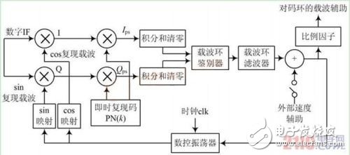
Figure 1 Block diagram of the GPS receiver carrier tracking loop
2 frequency discriminatorThe FLL completes the carrier stripping process by reproducing the satellite's approximate frequency. The sampling times of the signals I and Q should not cross the data bits. During the initial signal acquisition, the receiver does not know where the data hopping boundary is. While completing the bit synchronization, it is generally easier to maintain frequency lock with the satellite signal than phase locking. A commonly used frequency discriminator is a four-quadrant arctangent discriminator whose expression is:

Where: cr ss = I ps1 & TImes; Qps2 - I ps2 Qps1 ; dot = I ps1 & TImes; I ps2 + Qps1 & TImes; Qps2 ; I ps1 and Qps1 are correlation values ​​at time t 1 ; I ps2 and Qps2 are at time t2 Correlation value; t2-t1 is the pre-detection integration time.
With this discriminator, the correlation value samples at t1 and t2 should be in the same data bit time interval, but the receiver does not know the boundary of the data transition in the initial acquisition phase, so this paper uses the two-quadrant inverse tangent discriminator, which effectively prevents it. The frequency discrimination error caused by data hopping is expressed as:

The PLL performs the carrier stripping function by reproducing the exact phase and frequency of the satellite (converted to the intermediate frequency). Because the CoSTas phase-locked loop is not sensitive to data modulation, this paper uses the Costas phase-locked loop. The commonly used discriminators are shown in Table 1.
Table 1 Common Costas Ring Discriminator
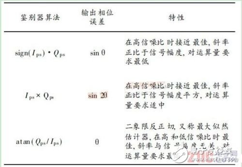
Since the input error range of the two-quadrant inverse tangent discriminator remains linear over the ±90° interval, a two-quadrant arctangent discriminator is used herein.
4 carrier loop filterThe function of the loop filter is to reduce the noise so that the original signal is accurately estimated. Its order and bandwidth determine its dynamic response to the signal. In order to adapt the receiver to a high dynamic environment, this paper uses a second-order FLL-assisted third-order PLL loop filter. The block diagram is shown in Figure 2.
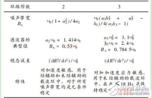
The characteristics of the loop filter are shown in Table 2.
After the receiver completes the acquisition and code tracking, it enters the carrier tracking module. Since the Doppler shift is large at this time, the FLL and the PLL work simultaneously, and the frequency difference and phase difference are input to the loop filter. When the frequency error is reduced to the PLL, Tolerate the range, set the input filter of the loop filter to zero, that is, the loop transitions to pure PLL tracking mode.
Table 2 Loop filter characteristics
From Figure 2, the expression of the loop filter is:

According to the environment of the receiver, the noise bandwidths Bnf and B np of the loop filter are determined, and the filter coefficients can be determined by Table 2. Note that the coefficient insertion point of the FLL to the filter is advanced by an integrator compared to the PLL because the unit of the FLL error is Hz and the unit of the PLL error is the phase unit.
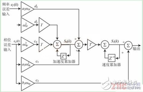
Figure 2 Second-order FLL-assisted third-order PLL filter
5 Simulation results and analysis5. 1 FLL discriminator characteristics
With pre-detection integration time T = 1 ms, with data modulation (±1 hop/ms), input frequency error range is ± 400 Hz, four-quadrant arctangent (atan2) and two-quadrant arctangent (atan) The discriminator is simulated and the result is shown in Figure 3. As can be seen from Figure 3, the atan2 discrimination algorithm can not identify the true frequency error, and atan can identify the range up to ±250 Hz.
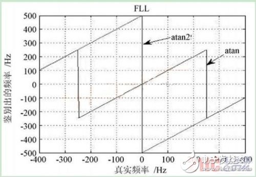
Figure 3: FLL frequency discrimination characteristics under data modulation
5. 2 PLL discriminator characteristics
Using the pre-detection integration time T = 1 ms, the input phase error range is ±180°, and the three phase discriminators of Table 1 are simulated. The results are shown in Fig. 4. As can be seen from Figure 4, only the two-quadrant tangent (atan) discriminator remains linear over a range of ±90°, and the slope is independent of signal amplitude.
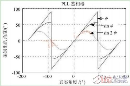
Figure 4 PLL phase discrimination characteristics
5. 3 carrier tracking loop simulation and analysis
Based on the simulation results in Sections 5.1 and 5.2, the FLL selects the two-quadrant inverse tangent discriminator, and the PLL also selects the two-quadrant arctangent discriminator. The discriminator result is sent to the loop filter shown in Figure 2, and the filtered result is sent to the numerically controlled oscillator to form the closed loop mode shown in Figure 1. The receiver captures a time domain and frequency domain two-dimensional search algorithm. According to the frequency discrimination range of the FLL discriminator, the frequency search step is set to 500 Hz. The simulation results for a receiver speed of 500 m/s and an acceleration of 10 g are shown in Figure 5. As can be seen from Figure 5, the carrier tracking loop can track the change of frequency quickly and accurately, and can reach the locked state in 3~4 s.
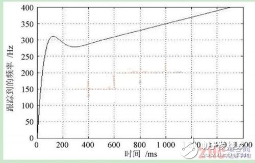
Figure 5 Tracked frequency curve
6 ConclusionA second-order frequency-locked loop is used to assist the carrier tracking loop of the third-order phase-locked loop. It can be seen from the simulation that the selected discriminator has a large identification range, high precision, and is insensitive to data hopping. The closed loop is formed by the discriminator, the loop filter and the numerically controlled oscillator. In the high dynamic environment, the loop locking time is short and the carrier measurement accuracy is high, which has certain practical value.
The Hydrogel Film is made of a honeycomb structure with super toughness TPU material, which has a certain buffering effect to prevent falling, explosion-proof, and collision with sharp objects. It is an innovative product with slow rebound technology. Small scratches and bubbles can be automatically repaired after 24 hours.
Self-Repairing Films,Automatically Repair Hydrogel Screen Protector,Self Healing Hydrogel Film,Hd Self-Repair Screen Protector,Hd Anti-Stress Repair Hydrogel Screen Protector
Shenzhen TUOLI Electronic Technology Co., Ltd. , https://www.hydrogelprotectors.com