The filter circuit is often used to filter out the ripple in the rectified output voltage. It is usually composed of reactive components, such as a capacitor C connected across the load resistor, or a series inductor L with a load, and various complexes composed of capacitors and inductors. Filter circuit.
Filtering is an important concept in signal processing. Filtering is divided into classical filtering and modern filtering.
The concept of classical filtering is an engineering concept based on Fourier analysis and transformation. According to the theory of higher mathematics, any signal that satisfies certain conditions can be regarded as being superimposed by an infinite number of sine waves. In other words, the engineering signal is a linear superposition of sine waves of different frequencies. The sine waves of different frequencies that make up the signal are called the frequency components or harmonic components of the signal. A circuit that allows only signal components in a certain frequency range to pass normally, while blocking another part of the frequency component, is called a classical filter or a filter circuit.
working principle
When the current flowing through the inductor changes, the induced electromotive force generated in the inductor will prevent the current from changing. When the current through the inductor increases, the self-induced electromotive force generated by the inductor coil is opposite to the current direction, preventing the increase of the current, and converting a part of the electric energy into a magnetic field can be stored in the inductor; when the current through the inductor is reduced, The self-induced electromotive force is in the same direction as the current, preventing the current from decreasing and simultaneously releasing the stored energy to compensate for the decrease in current. Therefore, after inductive filtering, not only load current and electricity
Circuit function
Circuit classification
Commonly used filter circuits are passive filtering and active filtering. If the filter circuit component consists only of passive components (resistance, capacitance, inductance), it is called a passive filter circuit. The main forms of passive filtering are capacitive filtering, inductive filtering and complex filtering (including inverted L-type, LC filtering, LCÏ€-type filtering and RCÏ€-type filtering, etc.). If the filter circuit is composed of not only passive components but also active components (bipolar transistors, unipolar tubes, integrated operational amplifiers), it is called an active filter circuit. The main form of active filtering is active RC filtering, also known as electronic filters.
Passive filter circuit
The passive filter circuit has a simple structure and is easy to design, but its passband amplification factor and its cutoff frequency vary with load, and thus are not suitable for applications where signal processing is required to be high. Passive filter circuits are commonly used in power circuits, such as DC power supply rectification, or LC (inductor, capacitor) circuit filtering for high current loads.
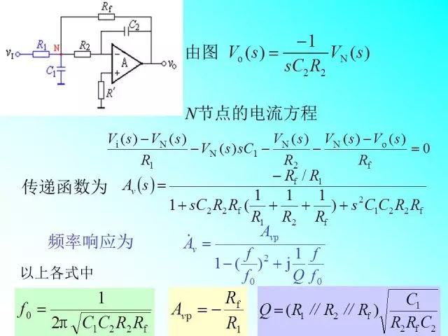
Active filter circuit
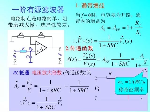
The load of the active filter circuit does not affect the filtering characteristics, so it is often used in applications where signal processing is required. The active filter circuit is generally composed of an RC network and an integrated operational amplifier, so it must be used with a suitable DC power supply, and can also be amplified. But the composition and design of the circuit is also more complicated. Active filter circuits are not suitable for high voltage and high current applications and are only suitable for signal processing.
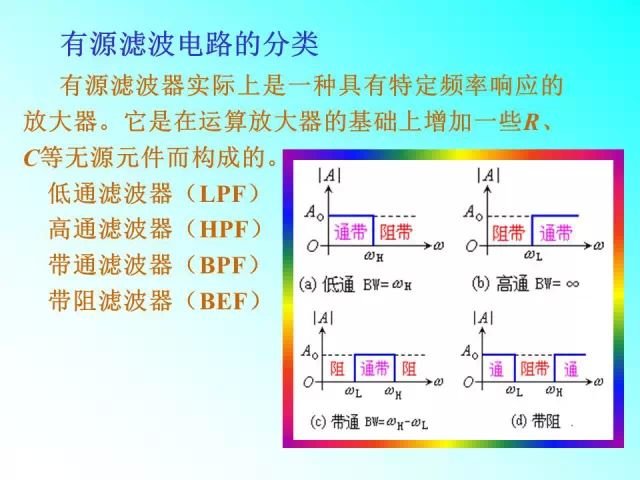
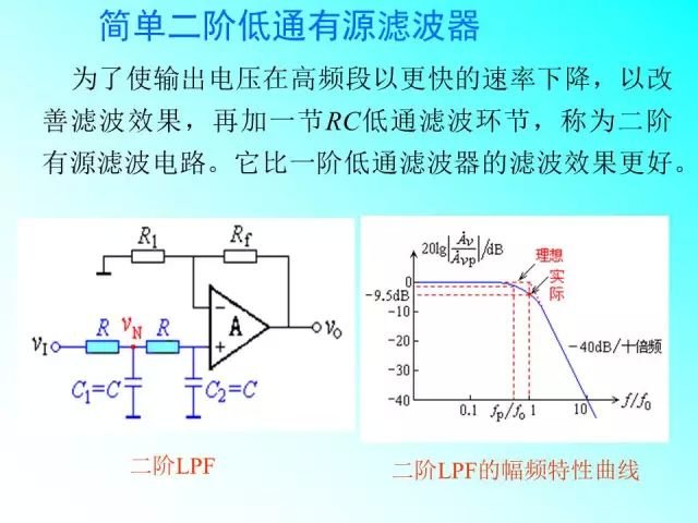
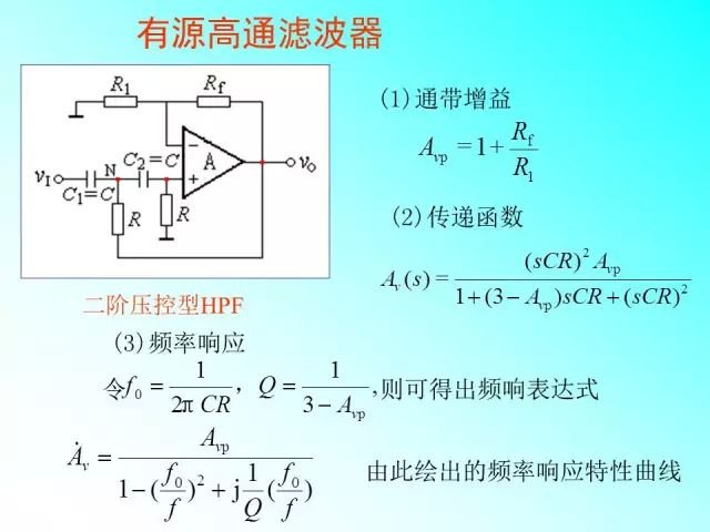
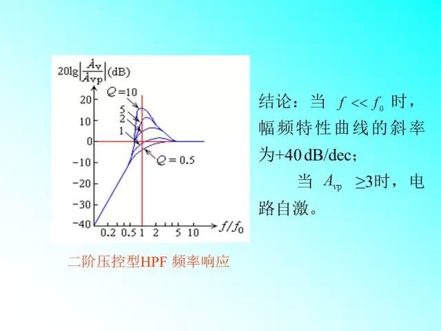
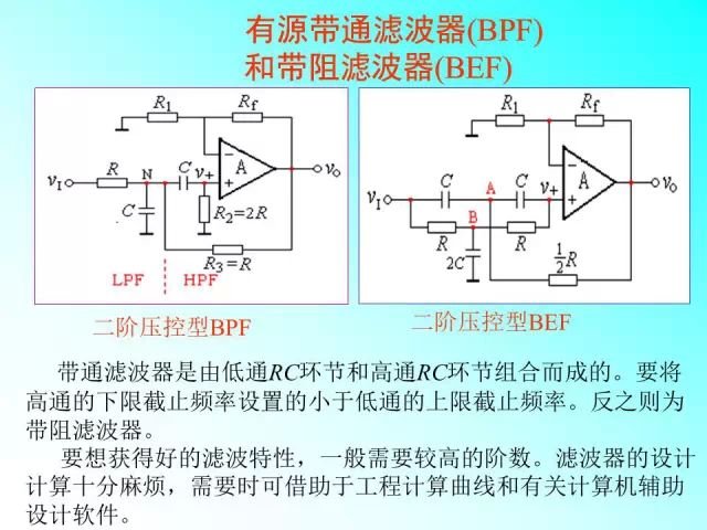
The method of identifying the filter is: if the signal frequency tends to zero, there is a certain voltage amplification factor, and when the signal frequency tends to infinity, the voltage amplification factor tends to zero, which is a low-pass filter; conversely, if the signal frequency tends to infinity When there is a certain voltage amplification factor, and the voltage multiplier tends to zero when the signal frequency tends to zero, it is a high-pass filter; if the signal frequency tends to zero and infinity, the voltage amplification factor tends to zero, then band-pass filtering On the other hand, if the signal frequency tends to zero and infinity, the voltage amplification factor has the same determined value, and if the voltage amplification factor tends to zero in a certain frequency range, it is a band rejection filter.
.
Commercial projectors are usually connected to the computer's VGA interface, HDMI interface, and U-disk interface, and perform large-scale presentation of the PPT, PDF graphic content, excel table content, or high-resolution image content that needs to be displayed. Many service and sales companies are equipped with business projectors, which are mainly used for holding small meetings, training employees, and explaining products to customers.
best business led projector,business 4k projector,business projector portable,business projector hd,business projector wireless
Shenzhen Happybate Trading Co.,LTD , https://www.happybateprojector.com