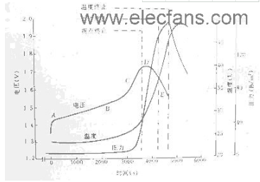
The charging characteristic curve of NiMH battery is shown in Figure 1. When the constant current is just charged into the discharged battery, the battery voltage rises rapidly due to the voltage drop of the internal resistance of the battery (point A). Thereafter, the battery begins to accept charge and the battery voltage continues to rise at a lower rate. Within this range (between AB), the electrochemical reaction produces oxygen at a rate that is also combined with hydrogen at the same rate, so that the internal temperature and gas pressure are low.
The self-made charger uses the four operational amplifiers of the LM324 as comparators. The voltage reference is set with TL431, and the S8550 is used as the adjustment tube to step down the input voltage and charge the battery. The principle circuit is shown in the figure. Its characteristics are simple circuit, reliable operation, no adjustment, easy to purchase components, etc. The following sections are introduced.
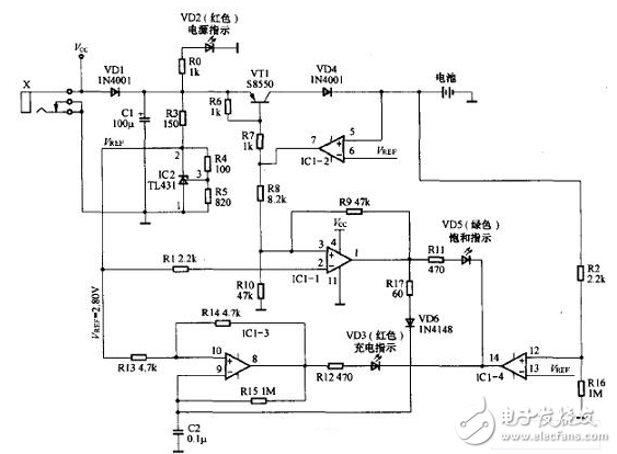
The external power supply is filtered by capacitor C1 after socket X and diode VD1. VD1 protects the TL431 from reverse polarity when the external power supply is reversed. R3, R4, R5 and TL431 form the reference voltage Vref. According to the parameter Vref=2.5&TImes;(100+820)/820=2.80(v), this data is mainly designed for Ni-MH rechargeable batteries (single-cell NiMH) The charged battery is fully charged with a voltage of approximately 1.40V).
2. High current charging(1) Working principle
When the power is turned on, the power indicator LED (VD2) lights up. Insert the battery (refer to the picture, actually lead to the battery box, the battery is installed in the battery box), when the battery voltage is lower than Vref, IC1-1 output low level, VT1 is turned on, output large current to the battery Charging. At this time, VT1 is in an amplified state - this is because the sum of the battery voltage and the -VD4 voltage drop is about 3.2V (assuming that the battery voltage is about 2.5V when charging starts), and the voltage after VD1 is about 5.OV, so VT1 The emitter-collector voltage difference is much larger than 0.2V. When the charging current is 300mA, VT1 heat is more serious. Therefore, it is better to use S8550 with PT=625mW, or increase the base resistance to reduce the charging current. Because the LM324 low-level drive capability is small, the measured IC1-2, IC1-4 output low level is not 0V, but is about 0.8V).
(2) indication of charging
First look at the operation of IC1-3: its non-inverting terminal 1O pin is connected to Vref through R13, R14 is connected to positive feedback, and the inverting terminal 9 is externally connected to the capacitor, and has a negative feedback path. Therefore, it actually constitutes a hysteresis comparator. At the beginning, there is no voltage at the upper end of C2, and IC1-3 outputs a high level. This high level has two discharge paths, one path is fed back to pin 10 through R14, and the other path is charged to capacitor C2 via resistor R15. When the charging voltage is higher than 10 pin voltage V+, the comparator flips output low. At the same time, due to the feedback effect of R14, the 10-pin voltage immediately jumps to V-. At this time, the capacitor C2 is discharged through the resistor R15. When the discharge voltage is less than the 10-pin voltage V-, the comparator flips the output again. Level, due to the feedback effect of R14, the 10-pin voltage immediately jumps to V+, after which the circuit repeats the above process. Therefore, the output of IC1-3 is a square wave signal with a fixed frequency.
Secondly, look at the working condition of IC1-4: the battery voltage is divided by R2 and R16, and connected to 12 feet of IC1-4. Because R2 "R16, the voltage of pin 12 of input IC1-4 is basically lower than the battery voltage.
Obviously it is lower than its l3 pin voltage, so the IC1-4 output is stable low. Combined with the above discussion, we can see that the R12 and VD3 paths are fixed at a fixed square wave voltage and the other end is a stable low level. Therefore, the LED VD3 will periodically illuminate, giving a flash The feeling of flashing.
Finally, look at the working condition of IC1-1: When IC1-2 outputs low level, it is obvious that pin 3 of IC1-1 is low level, and its 2 pin is connected to Vref through R1, so IC1-1 also outputs low level. Combined with the above discussion, we can see that the voltage difference between R11 and VD5 is zero, so VD5 (saturation indication) can not be lit!
In addition, since IC1-1 outputs a low level, no matter how the voltage of pin 9 of IC1-3 changes (capacitor charge and discharge form a triangular wave voltage at this pin), it will not be affected by IC1-1 output - because IC1-3 9 The pin voltage (either high to V+ or low to V-) is always higher than the output of IC1-1, and VD6 is reverse biased! Therefore, in this state, the operation of the three indicators is: VD2 is lit, indicating that the power is normal; VD3 is flashing, indicating that the battery is charging normally; VD5 is not lit.
3. Small current chargingWhen the battery voltage gradually rises to near Vref after charging for a period of time, the output voltage of IC1-2 rises slowly, so the current flowing through R7 gradually decreases, that is, the current flowing through the base of VT1 gradually decreases. Therefore, the current output of VT1 will gradually decrease, but the battery voltage will continue to rise slowly. When the battery voltage is almost equal to Vref, IC1-2 will output a higher voltage. At this time, IC1-1's 3-pin voltage is high. At 2.8 OV (inverting terminal 2 pin input voltage), the comparator flips the output high. This voltage has two functions: on the one hand, VD5 forward bias is turned on (at this time, IC1-4 output is still low), indicating charge saturation; on the other hand, VD6 is also positively turned on, and R17 is very Small, actually, the upper end of C2 is forced to be high level, so the voltage of pin 9 of IC1-3 is higher than the voltage of 10 pin, IC1-3 is forced to output low level, and VD3 is extinguished because there is no positive bias.
Although, from the external performance, the charging lamp is extinguished, the saturation lamp is turned on at a certain moment, but the charging process is gradually transitioning: when the battery voltage is much lower than Vref, the current is continuously charged, when the battery is charged. When the voltage is close, the charging current is slowly reduced until the charging gradually approaches zero - even if the saturation lamp is lit, the small current charging continues! Therefore, in this state, the working conditions of the three indicators are: VD2 is lit, indicating that the power is normal; VD3 is not lit; VD5 is lit (saturation indication, small current charging).
The feedback letter ^L3W current sampling is connected to the two input terminals of the operational amplifier. The signal jâ–³ makes the current of the current dRsc maintain the water sitting output current as follows:
Lout=(VLn/Rsc)(R:/Ri)
Select RfR4-Ikn, Ri:RilOOkn. Rsc = 0, 25n. Thus, when the input voltage is 6, 25V, an output current of 2.5A can be given. Ri-Ra is a 1% error, 0.25W resistor, and the op amp should be attached to the heat sink.
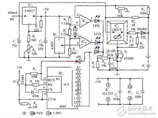
The charging circuit generates a temperature rise, especially when the charging circuit and the rechargeable battery are heated up at a high current. The LTC4060 external thermistor can detect the charging temperature to avoid overheating. The LT4060 has a temperature-controlled 2A NiMH battery charger as shown.
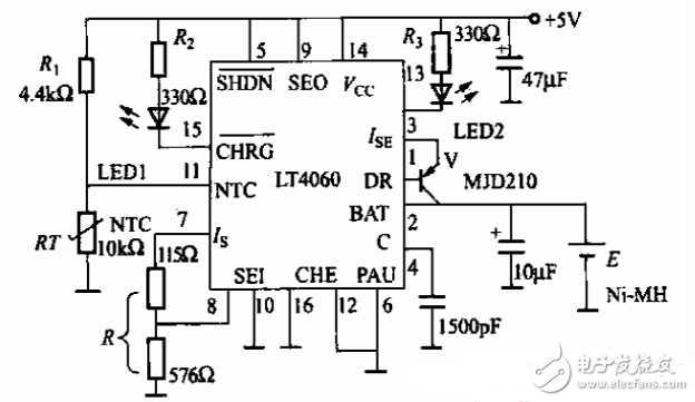
RT and LT4060 internal circuit constitute temperature detection circuit, RT is a negative temperature coefficient thermistor, you can choose a thermistor with a resistance of lOkn at 45 °C, close to the surface of the battery. When the temperature is high, the LT4060 will automatically reduce the charging current. When the temperature rises to 55 °C, the charging will stop automatically.
LED1 is the charging indicator and LED2 is the "charge full" indicator. 7 feet set the maximum charging current, III. =1395/R, 8 feet set the maximum charging voltage. The LT4060 has a charging current of o_4—2A and a supply voltage range of 4.5N10V. It can charge nickel-metal hydride and nickel-cadmium rechargeable batteries.
A single NiMH battery has a voltage of 1.25V and a maximum of 1.55V during charging. It should not be charged with a DC power supply higher than 3V. The power transformer is output as a double-winding of 3.5V AC for full-bridge rectification to obtain positive and negative 3.5V DC, with the negative terminal output as the zero level, and the midpoint becomes +3.5V, which can be used as the DC power source for charging the NiMH battery. The positive output becomes +7V and can be used as the operating power for the control circuit. At the non-full load output condition, the midpoint level is approximately 4.9V and the positive output is approximately 9.8V. At full load output, the midpoint level is 3V and the positive output is approximately 7.9V. The COMS gate circuit CC4093 and the general-purpose quad op amp LM324 used in the control circuit can work normally between 6V and 12V.
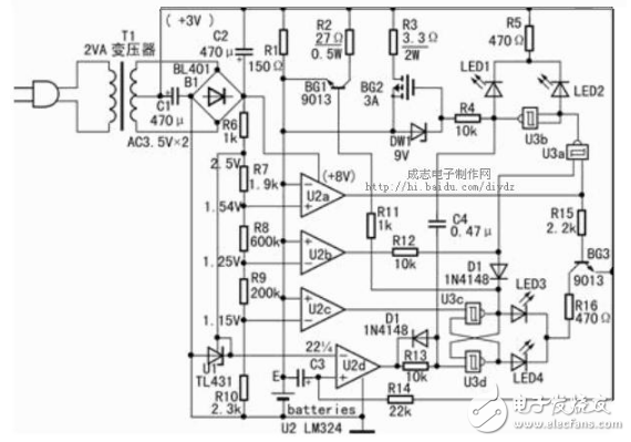
Referring to the schematic diagram, U1 is a voltage-stabilized integrated circuit TL431 with a built-in voltage comparator that provides a 2.5V precision reference voltage. Four resistors from R7 to R10 are divided in series to provide 1.54V, 1.25V, and 1.15V comparison voltages for the three voltage comparators U2a, U2b, and U2c. The negative input terminal of U2a and the positive input terminal of U2b and U2c are connected to the positive terminal of the nickel-hydrogen battery to detect the voltage across the battery. When the battery voltage is higher than 1.54V, U2a outputs a low level. When the battery voltage is lower than 1.54V, U2a outputs a high level. When the battery voltage is higher than 1.25V, U2b outputs a high level. When the battery voltage is lower than 1.25V, the U2b output is low. U2c outputs a high level when the battery voltage is higher than 1.15V, and U2c outputs a low level when the battery voltage is lower than 1.15V. The negative input terminal of U2d is connected to the 2.5V reference voltage, and the positive input terminal is connected to the neutral power supply through the R24 resistor. At the same time, the U2d positive input terminal is connected to the positive terminal of the NiMH battery through the C3 capacitor. After no battery is placed or powered on for a few seconds, U2d outputs a high level.
When the battery is placed in the circuit, the power is turned on. The positive input terminal of U2d is temporarily short-circuited by the C3 capacitor and connected to the positive terminal of the nickel-hydrogen battery. The level is not more than 1.5V, U2d outputs low level; after about 1 second After that, the C3 capacitor is charged, and the U2d positive input terminal level is higher than 2.5V, and U2d outputs a high level. If you put a battery that can be used without discharging power, U2c will detect that the voltage across the battery is higher than 1.15V and output high level. When U2d still outputs a low level, the RS flip-flop consisting of NAND gates U3c, U3d will be set to U3c output low level, U3d output high level. After 1 second, U2d outputs a high level, and the output states of U3c and U3d remain unchanged. The LED 4 emits red light to indicate that the battery does not need to be charged. The U3c output low level makes BG1 cut off, the NAND gate U3a input terminal is blocked output high level at the same time, the NAND gate U3b outputs low level, and the power FET BG2 is cut off. Only the current of about 30 mA through R1 gives the battery a turbulent maintenance charge.
If a discharged battery is placed, U2c will detect that the voltage across the battery is below 1.15V and output low. When U2d still outputs a low level, the RS flip-flop consisting of NAND gates U3c and U3d will be set to output high level for both U3c and U3d. But after 1 second, U3d is changed to output low level, and U3c continues to maintain output high level. The green LED of the LED 3 indicates that the battery needs to be charged. At this time, U2b outputs a low level to make U3a output a high level, U3b outputs a low level, and power FET BG2 is turned off. However, U3c outputs a high level to turn BG1 on, and supplies about 100mA current through R2 and 30mA current through R1 to charge the battery for small current. After the battery starts charging, the output state of U2c is turned to a high level while the battery voltage is higher than 1.15V and lower than 1.25V. However, the output states of U3c and U3d remain unchanged, U3c continues to output a high level, and BG1 is turned on. Because U2b's output state is still low, U3a outputs a high level, U3b outputs a low level, and power FET BG2 is turned off. The battery is still charged with a current of only about 100 mA through R2 and a current of 30 mA through R1.
After a period of low current charging, the battery voltage is higher than 1.25V and lower than 1.54V. The voltage comparators U2a and U2b both output a high level. At this time, U3c also continues to output a high level, so that U3a outputs a low level. U3b outputs a high level, and the power FET BG2 is turned on. The R3 provides a current of not less than 500mA and a current of 100mA supplied by R2 and a current of 30mA supplied by R1 to charge the battery with a large current. At this time, the LED1 emits green light and is in a state of high current charging, and the LED3 green light-emitting tube is extinguished. The light-emitting tube LED2 is also extinguished.
After a period of high current charging, the battery is fully charged. When the battery voltage is higher than 1.54V, U2a outputs a low level to make U3a output high level, U3b outputs low level, and power FET BG2 is cut off. LED1 is off and LED2 is on. At the same time, U3b is flipped from a high level to a low level, and the U3d input terminal is temporarily turned low by a differential circuit composed of a C2 capacitor and R13, thereby turning the U3b output terminal from a low level to a high level. . LED4 illuminates that the battery is fully charged. The output of U3a is flipped from a high level to a low level, LED3 is turned off, and BG1 is also turned off. Only the current of 30 mA through R1 continues to charge the battery. If the trickle charge is continued, the battery voltage will be reduced from 1.55V to 1.5V, and the output terminals of U2a and U2b will output a high level. However, the U3a input terminal has been blocked by U3c and can only output a high level. U3b output Low level, the power FET BG2 continues to be turned off, and only the 30 mA current through R1 continues to trickle charge the battery.
After the battery is removed or the power is turned on without the battery inserted, the E point of the positive terminal of the battery is connected to the midpoint potential higher than 1.55V, U2a outputs a low level, BG3 is turned off, and LED3 and LED4 are not illuminated. At this time, U3a outputs a high level, U3b outputs a low level, and LED2 emits a red light indicating that the circuit is in a power-on state, and LED1 does not emit light. Then put the battery and repeat the above automatic detection charging process.
Among them, LED1 and LED2, LED3 and LED4 can be combined with a two-color light-emitting tube. When the power is turned on, LED1 and LED2 always have one light. LED3 and LED4 must have a battery to emit light, so it can be judged whether the battery is placed and no contact failure occurs.
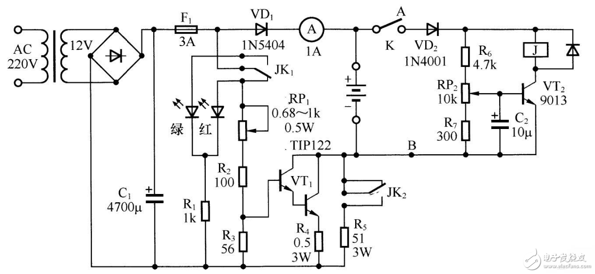
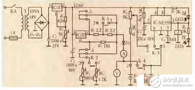
The figure shows the 7.2V, 2700mAh nickel-metal hydride battery (6-series series) charger circuit. The red LED is on during the power-on and charging process of the charger; the green LED is on when the battery is fully charged. RP1, R2, R3, R4, and VT1 form an adjustable constant current source (VT1 is a Darlington transistor). Adjusting RP1 can continuously change the charging current from 0 to 1A. R6, RP2, R7, C2, VT2 and J form a voltage detection circuit. When the battery voltage rises to the set value during charging, VT2 is saturated, J is electrically connected, contact JK; switching position makes VT1 The bias is turned off and the green LED is on, indicating that it is fully charged. At the same time, JK2 also switches position, so that R5 is connected to the charging circuit to perform trickle charging of the battery pack by about 100mA. The trickle charge current of a nickel-hydrogen battery is generally 2% of its capacity, and the trickle charge current of a nickel-cadmium battery is generally 1/16 of its capacity.
Fiber Optic Connector,Fiber Connector,Fiber Termination,Fiber Adapter
Huizhou Fibercan Industrial Co.Ltd , https://www.fibercan-network.com