300B single-ended power amplifier is famous, people are loved, and the production circuit is endless, and the competition is splendid. The circuit introduced this time is relatively simple and traditional, mainly focusing on reducing the humming sound generated by the filament AC power supply to improve its sound quality.
First, the circuit introduction300B is a direct heating power tube, and the filament heating has two ways of AC or DC power supply. Both filament heating methods have their own advantages. It is generally believed that in terms of sound quality, AC heating is advantageous, and the disadvantage is that the AC sound is larger than that when DC heating. Therefore, if the 300B filament is heated by AC, try to minimize its residual noise, then it is possible to achieve better sound quality. In order to reduce the 300B residual noise, the easiest way is to avoid using the negative feedback loop from the secondary winding of the output transformer to the front stage, or to minimize the negative feedback, it is best to cancel the negative feedback loop. This circuit uses AC heating for the 300B filament, and cancels the negative feedback and pays attention to the design of the voltage amplification stage in order to obtain better sound quality.
Figure 1 is a circuit diagram of the machine. In addition to the different conventions in some places, it can be said that it is a very traditional circuit structure. The entire circuit is quite simple, eliminating unnecessary components and circuits as much as possible, reducing the number of components. The general application values ​​and characteristics of the tubes used in the whole machine are shown in the attached table.
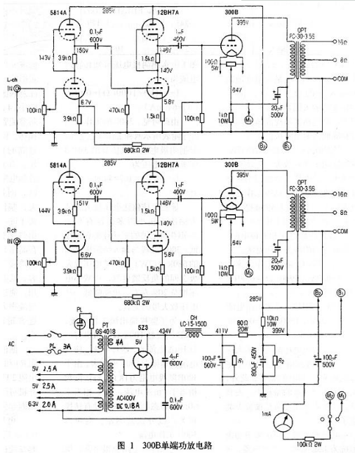
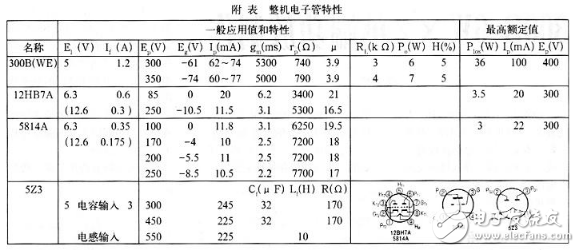
The power amplifier adopts two-stage voltage amplification, and both adopt SRPP circuit structure. SRPP was originally developed for high-frequency amplification, and it is now used for low-frequency amplification circuits, which is of course expected to achieve a wider frequency response. Since the noise amplified by the triode is smaller than that of the pentode, the two-stage voltage amplification of the machine uses a triode. The input stage deliberately chose the double transistor 5814A, which is equivalent to the 12AU7 high performance tube, in order to minimize the amplification noise of the input stage. Due to the low amplification factor (μ) of the 5814A, the SRPP circuit can increase the gain of this stage and reduce its output impedance. The second stage voltage amplification uses 12BH7A, which is suitable for audio amplification, oscillation and pulse amplification, and thus has good performance guarantee as a low frequency application. The operating current of this stage is relatively large, in order to provide sufficient driving force for 300B. According to the 5814A, 12BH7A cathode voltage and cathode resistance in Figure 1, their quiescent operating current can be estimated.
(1) 5814A static working currentI=6.7(v)/3900(Ω)=0.0017(A)=1.7(mA)
(2) 12BH7A static working currentI=5.8(V)/1500(Ω)=0.0038(A)=3.8(mA)
The maximum output voltage of the above two-stage voltage amplification (before the clipping point) reaches 90V, which is enough to meet the needs of pushing 300B. In addition, the two-stage voltage amplification stage has low noise and low distortion, which lays a foundation for the whole machine to adopt non-negative feedback amplification.
The power output stage 300B uses an output transformer with a primary impedance of 3.5kΩ. From the measured cathode voltage in Figure 1, the quiescent current is I=64(V)/1000(Ω)=0.064(A)=64(mA).
It can be seen that the working state of 300B is between the two working states shown in the attached table. According to the cathode voltage, the 300B gate pushing voltage can be estimated as U=64(V)&TImes; 0.7=44-8(V)≈45(V). Obviously, this value is much smaller than the maximum output voltage of the voltage amplification stage, which is advantageous for 300B to obtain sufficient drive and low distortion. The 680kΩ (2W) resistor between the 300B gate and the input stage cathode is a negative feedback resistor between the voltage amplification stages, which reduces the voltage gain by about 200 and also reduces the distortion of some voltage amplification stages.
To monitor the output stage operating current, the 300B cathode has a 1 mA ammeter through a 100kΩ resistor string. In this way, the ammeter is converted to a 100V voltmeter. Since the 300B cathode resistance is lkΩ, the reading per volt is equivalent to the lmA current. 60V is equivalent to 60mA quiescent current. The meter is provided with a changeover switch to monitor the operating current of the left and right channels 300B, respectively.
The power supply part of the circuit is also very common, but the value of the filter component has a certain influence on the local hum, so it should be given enough attention. First notice that the capacity of the filter input capacitor is small (4μF/600V oil immersion capacitor) to prevent the surge current flowing through the rectifier from being too large and damaged. At the same time, it also prevents excessive DC high voltage damage related components. In order to reduce the high-voltage ripple, a two-stage 滤波-type filter circuit composed of an inductor and a resistor is used, and the capacity of the filter capacitor is quite large, so that sufficient attention must be paid during production to further reduce the hum, especially the hum generated by the filament AC power supply. A 20uF/500V electrolytic capacitor is connected between the high-voltage B1 and 300B filament center points to achieve a certain reverse cancellation effect. Through the above measures, the hum of the whole machine is greatly reduced, and even if the ear is close to the speaker, the residual noise is completely inaudible. The resistors R1 and R2 connected in parallel on the filter electrolytic capacitor (each of which is connected in parallel with 270kΩ/6W resistors) are leakage resistors. The startup can prevent excessive transient voltage, and the function of discharging high voltage after shutdown. The voltage amplifier stage filament winding is grounded through a 0.1μF/600V capacitor, mainly for AC grounding.
The electrical specifications for resistors and capacitors are indicated in Figure 1. The unspecified resistors are all 3W oxide resistors, and those above 3w are tantalum resistors. The requirements for the windings of the power transformer are also indicated in Figure 1. Both the output transformer and the filter choke have been marked with the model numbers. They are all products of the Hirata Electric Manufacturing Co., Ltd., which are not easily purchased in China. For this reason, their main specifications are listed.
(1) Output transformer: rated output power 40w, primary side impedance 3.5kΩ, primary side DC resistance of about 66Ω, primary side inductance minimum 20H (maximum 26H), allow Dc current 1 70 mA, frequency response 20Hz ~ 100kHz / -2dB (Test condition input 4V, rp=Zp).
(2) Choke: Inductance 15H, DC resistance 165Ω, rated current 150mA (current allowed 200mA). When copying, you can select similar products according to the above specifications or commission processing according to the above requirements.
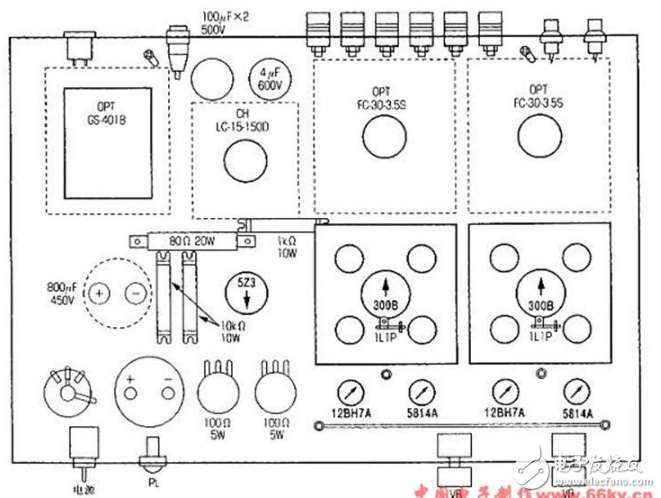
Figure 2 shows the chassis and its front and rear machining drawings. It can be made with a 2.0mm thick aluminum plate. Of course, all the components should be purchased before the specific processing, and then the processing size should be appropriately modified according to the actual size of the device used. In order to facilitate the good heat dissipation of 300B, a small mounting plate was specially processed for it. The processing dimensions are shown in Figure 3. The thickness of the plate is 1.5mm aluminum plate. The 300B and its installation method are clearly shown in the figure.
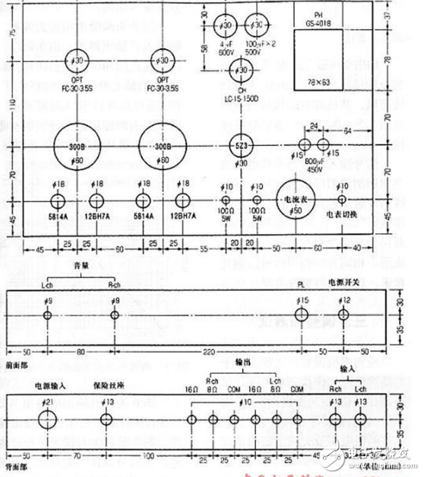
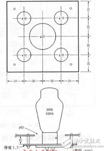
Figure 4 is a layout view of the main components under the chassis. The pipe sockets should pay attention to the installation direction, which is indicated by small arrows in Figure 4. For 300B and 523, the direction indicated by the arrow is the direction of the filament of the tube, which is the direction between pins 1 and 4. For 5 8l 4A and 12BH7A, the direction indicated by the small arrow is the direction between pins 1 and 9. Two grounding points are installed on the chassis, one is the "signal grounding point", arranged at the signal input terminal; the other is the "power grounding point", arranged at the power transformer, as shown in Figure 4. In addition, a long grounding busbar (a 1.5mm bare copper wire) can be arranged near the 4 tubes of 5814A and 12BH7A. It should be noted that the above two grounding points should ensure reliable electrical contact with the chassis. Generally, the site should be carefully cleaned of dirt, and then the grounding lugs should be tightly fixed by screws. For the grounding busbar, care should be taken not to make electrical contact with the chassis. The busbars should generally be "overhead" at the ends of the busbars with terminals insulated from the chassis. Since the ground bus is a "signal" ground, the ground bus needs to be separately wired to the solder tab of the "signal" ground.
The gate resistance (100kΩ) of the 300B is soldered to the header gate pad of the stem, and the other end is soldered to the bracket lL1P fixed at the stem, and then connected to the ground bus by the wire. The coupling capacitance between the 12BH7A and the 300B (1μ/400V) is directly connected to the corresponding pins of the two tubes. Since the capacitor is bulky, it should be fixed by wrapping the metal sheet (note the insulation from the chassis).
The distance between the 300B screen and the output transformer is far, and it is better to use a plastic hard wire of 1.5mm or more to connect it. The grounding terminal of each component of the power supply part, the center tap of the high-voltage winding of the power transformer, etc., can be connected to the “power grounding point†by the 1.2ram multi-strand soft wire. On the secondary side of the output transformer, the wiring of the DC high voltage part is connected by a 1.2mm multi-strand soft wire. Wiring of other parts may be connected by a 0.5-0.75mm multi-strand cable as the case may be. The signal input terminal and the volume potentiometer are connected by a shielded wire as usual. The shield of the shielded wire should be connected to the “signal grounding point†terminal separately, and the exposed shielding layer should not be in contact with the chassis. After the wiring is completed, the leads in the same direction can be bundled, which makes them look neat and tidy.
three. Adjustment and testingSpeaking of the adjustment of the machine, in fact, because the circuit is simple and the working state is guaranteed by the design, as long as the installation is correct, almost no adjustment is needed. If you think the gain is high, just adjust the negative feedback resistance (680kΩ) between the two stages of voltage amplification. However, after the installation is complete and powered up, test the voltage of each tube as usual. From the measured voltage in the figure, except for the input stages of the left and right channels are slightly different, the left and right channels of the other tubes are identical. Then, based on the measured voltage, the actual power consumption of each tube (tube pressure drop × quiescent current) can be calculated.
Input stage 5814A P: 6.7 (V) / 3900 (Ω) × [143 (V) - 6.7 (V)] = 0.23 (W)
Driver stage 12BH7A P=5.8(V)/1500(Ω)x[140(V)-5.8(V)]=0.5(W)
Output stage 300B P=64(V)/1000(Ω)×[395(v)-64(v)]=21.1(W)
Obviously, the above values ​​are far less safe than the highest rated value P1os of each tube shown in Table 1.
Figure 5 shows the input/output characteristics of the two-stage voltage amplification stage itself. It can be seen from the figure that the clipping point is about 90V. It has been estimated that the maximum driving voltage of 300B is about 45V. It can be seen from Fig. 5 that the output of about 50V can be achieved when the input is 1V, which fully demonstrates that the voltage amplification stage of the machine has sufficient driving capability.
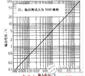
Figure 6 shows the input/output characteristics of the whole machine when the output stage of the machine is WE-300B. The tube was not selected at the time of production and is roughly considered to reflect the average performance of the WE-300B. It can be seen from Fig. 6 that the input 1V signal voltage can reach 6W without clipping output power, and the maximum output can reach more than 8W.
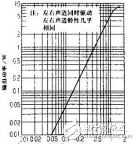
Figure 7 shows the frequency response curve of the whole machine. When the output is 1W, the curve is almost the same as the output transformer itself. When the 6W output is only the high frequency end falls slightly faster.
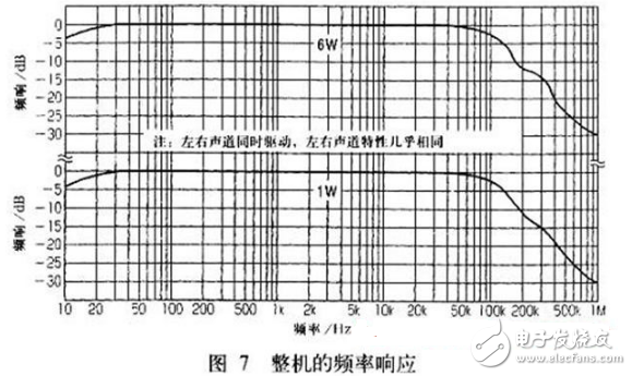
Figure 8 shows the damping coefficient characteristic curve of the machine. The damping coefficient is 4 in the range of 100 Hz to 20 kHz, and only the low frequency end and the high frequency end slightly decrease.
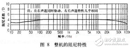
Figure 9 shows the distortion characteristics. Since the output stage has no negative feedback and has soft distortion characteristics, the 100 Hz to 10 kHz distortion curve shows almost the same tendency. The 1 kHz and 10 kHz distortions are almost the same, and the 100 Hz distortion is only slightly deviated from the 1 kHz and 10 kHz curves when the output power is small ("2W"). This property can also be said to be the common tendency of all 300B pipes.
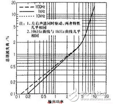
Figure 10 shows the square wave response (top curve) when the unit is connected to various capacitive loads, and is tested using a 10 kHz square wave. The lower curve in the figure is the square wave response at pure resistive load for comparison.
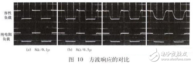
It can be seen from Fig. 10(a) that the capacitive load of 0.1 μF is almost the same as that of the pure resistive load. The square wave responds to the left corner with a "ringing" at 0.5μF load, but the overshoot is very slight. The load capacity is increased to lμF and the waveform ringing is slightly dull. When the load capacity is increased to 2 μF, the waveform is further blunt to appear "rounded". It can be seen from the above test waveforms that when the speaker is connected to various speakers with different load characteristics, abnormal oscillation will not occur, and the work is stable and reliable.
four. Performance comparison.There are two main intents for the design of this machine. In order to reduce the hum of the direct heating power tube, the current 300B filament is increasingly popular with direct current heating. One of the intentions of this machine is to reduce the hum sound level by properly designing the circuit, and also the original sound quality of the 300B filament AC heating. At the same time, in view of the subjective sound quality evaluation of the '300B single-ended power amplifiers of various departments, there are many different opinions. The second intention of this machine is to select several different 300Bs for some main performance tests based on the above circuits, and take a look at them. There are similarities and differences between the two, providing some objective basis for subjective evaluation. Before performing performance comparison, it is first stated that the test performance data given above is the case when WE-300B is used. Although it is a "wE" model, it is not the original brand produced by WE (Western Electric) in the 1940s, but the closest replica of the performance index to the original brand. The STC-4300A produced in the UK is not exactly the same as the WE-300B in the tone, but the technical indicators of the two are basically the same. Therefore, relatively speaking, the sound quality and performance of 300B produced in other countries can generally be compared with the above two models of 300B as a benchmark.
Chinese enthusiasts are very concerned about the sound quality and performance of the domestic 300B, and are also the preferred brand at the time of production. To this end, the measured performance of the domestic 300B application of the circuit of Figure 1 is given below for comparison. Of course, the domestic 300B has not been selected, which can reflect the general quality level.
Figure 11 shows the input/output characteristics of the domestic 300B. Obviously, it has higher power sensitivity than the WE-300B. Similarly, under the condition that the input signal is 1V, the domestic 300B output power is 1W higher than WE-300B.
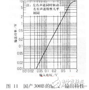
Figure 12 shows the frequency response of the domestic 300B. It has declined since 30 kHz, while the WE-300B has started to fall from 50 kHz. However, both -3dB points are approximately 100kHz.
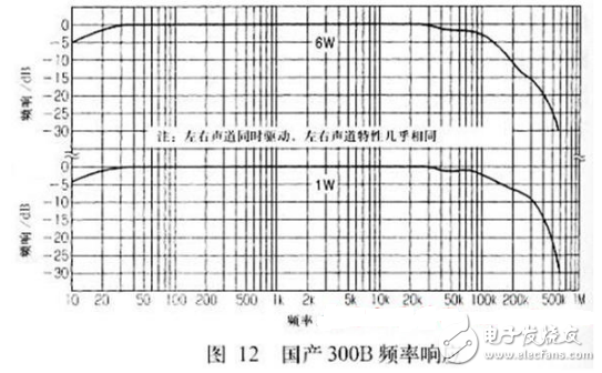
Figure 13 shows the damping characteristics of the domestic 300B. The shape of the curve is very similar to that of the WE-300B. The damping coefficient is roughly reduced by about 0.4.
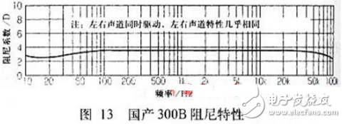
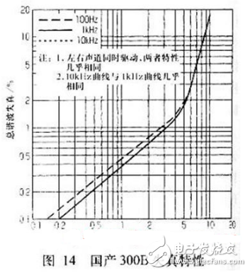
Figure 14 shows the distortion characteristics of the domestic 300B. It is also very similar to the WE-300B, but the 300B distortion is slightly smaller at lower output power, and the opposite is true at higher output power, that is, the WE-300B distortion is slightly smaller.
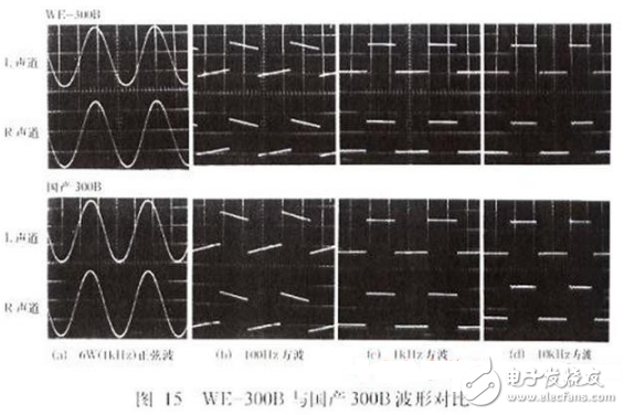
From the above four test performance, compared with WE-300B. The internal resistance and interelectrode capacitance of the domestic 300B are slightly larger, but the two are still very similar. Figure 15 is a comparison of the waveforms of WE-300B and domestic 300B. Fig. 15(a) shows the sine wave waveform at the 6W output. No clipping is seen, and there is a certain margin.
Insulator Fitting Cap,Ball Clevis Fitting for Insulators,Galvanized Ball Eye Ball Clevis
TAIZHOU HUADONG INSULATED MATERIAL CO.,LTD , https://www.thim-insulator.com