The electromagnetic torque of a DC motor is a function of the armature current. The current is affected by various factors such as the rotational speed and the load torque. It is a complicated conversion process. Therefore, the key to the control of the DC brushless motor is the control of the current loop, that is, the current closed loop control and the current rate change control. Not only must meet the accuracy requirements, but also meet the speed requirements. In particular, the control of the current rate of change requires a very fast response.
2, the design of the control systemIn some special application environments, such as elevators, lifting, traction, etc., the start, stop and operation of the drive and drag system are required to be very stable to enhance comfort and safety. Figure 1 is a typical closed-loop control system. In the figure, Vgn is the center control microcontroller given speed, Vfn is the feedback speed, and the difference between the two is generated by the speed regulator to give the given current signal Vgi. The closed loop is called speed adjustment. ring. Vgi and the current Vfi detected by the Hall current sensor HL are differenced and then enter the current regulator LT. The regulator is adjusted under the maximum current limit, and the output waveform control signal Vgb is controlled by the current rate change control circuit LBT. A PWM pulse that drives the IGBT is generated. The current change rate signal is generated by differentiating the current signal from HL through the differential circuit LD, and Vgb is adjusted in the LBT to limit the increase in the current change rate. In the control system shown in Fig. 1, the inside part of the dotted line frame is designed using UC3846. The following describes the design principles.
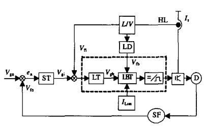
Figure 1 Closed loop control block diagram
2.1, current type controller principleIn addition to the full function of the voltage type PWM controller, the current type controller also needs a current detection link. The detection point can be arbitrarily selected according to requirements, such as the switching tube current, the inductor current or the total output current sent by the HL sensor. . The following uses UC3846 as an example to illustrate its working principle. Figure 2 shows the internal structure of the chip. The difference between the figure and the voltage type control device is that a current measuring amplifier is set with a gain of 3. The E/A amplifier is an error amplifier. The output is diode-biased and biased to 0.5V and sent to the opposite end of the comparator. The current measurement signal is three times after the non-inverting terminal. The output of the current measuring amplifier is limited to 3.5 V or less by the internal circuit, and therefore, the maximum voltage value of the current measuring signal is limited to 3.5/3 = 1.2 V. The current measurement link parameters can be selected according to 1.2V. For current mode control, in order to ensure that the output current is constant and is not affected by the duty cycle d, slope compensation must be performed. The method is: superimposing a sum of a triangular waveform derived from an oscillator waveform and an inductor current waveform at the input of the current detecting amplifier (4 feet) or the output of the error amplifier (7 feet), that is, the slope compensation is completed, and the amplitude thereof should be Greater than l/2 of the slope of the current waveform.
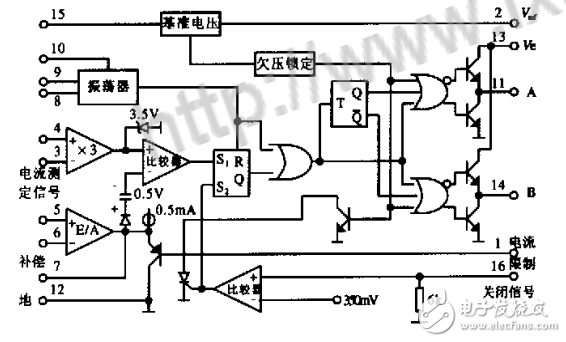
Figure 2 Internal structure of the UC3846
Figure 3 shows the schematic diagram of the internal and external circuit connections of the UC3846. In the figure, S is a PWM register, and there are two set terminals S1 and S2, which can make y. . Is high, blocking the PWM output. In the design, the output of A is accepted by sl. When the output current I is greater than the given value, the output of A3 is high, thus forming the trailing edge of PWM. The S2 terminal accepts control of two control signals K1, K2 formed by an external circuit. K1 is used as the circuit to turn off, and K2 is the output of the output detection current I through the differential circuit. The function is to turn off the pulse output when the current change rate exceeds a certain value. In the figure, R5C. constitutes a slope correction network to correct the output current. The working principle of the current loop and the current rate change loop are discussed separately below.
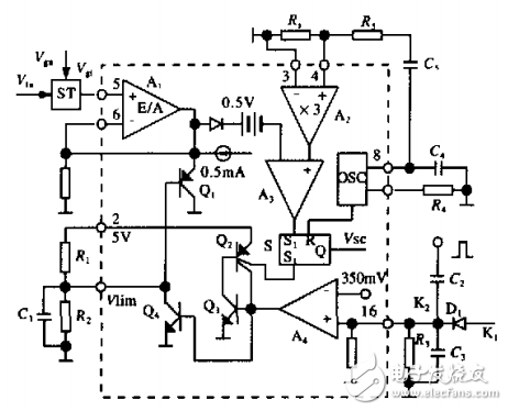
Figure 3 Part of the uc3846 internal structure and external connection diagram
A comprehensive selection of USB connectors are available with various combinations of form factors, interface and version types, vertical and horizontal configurations, as well as a unique new USB 2.0 Type-C charging option. Chances are Antenk have the right USB connector for you.
USB (Universal Serial Bus) was originally developed and introduced in 1996 as a way of setting up communication between a computer and peripheral devices by replacing many varieties of serial and parallel ports.
USB connectors have become the standard connection method for devices such as mice, keyboards, game pads & joysticks, scanners, digital cameras, printers and external hard drives.
Although designed for personal computers USB has become commonplace on other devices such as mobile phones, PDA's, video game consoles, AC power adaptors, memory sticks and mobile internet access dongles.
USB Connector Type
USB Type A
Also known as USB standard A connector, the USB A connector is primarily be used on host controllers in computers and hubs. USB-A socket is designed to provide a "downstream" connection intended for host controllers and hubs, rarely implemented as an "upstream" connector on a peripheral device. This is because USB host will supply a 5V DC power on the VBUS pin. As such, it is important to remember while purchasing USB cables it is safest to make sure at least one of the plugs is a USB A.
Though not that common, USB A male to A male cables are used by some implementers to make connections between two USB A style female port. Be aware that typical A-A cables are not intended for connection between two host computers or computer to hub.
Related Products:
USB 2.0 A to A Female Cables
USB 2.0 A to B Cables
USB 2.0 A to Mini B Cables
USB 2.0 A to Micro B Cables
USB 2.0 A to A Angle Cables
USB 2.0 A to B Angle Cables
USB 2.0 A to Mini B Angle Cables
USB 2.0 A to Micro B Angle Cables
USB 2.0 A to B Locking Cables
USB 2.0 A to Mini B Angle Cables
USB 2.0 A Female to A Cables
USB 2.0 A Female to Crimp Housing Cables
USB 2.0 A to B High Flex Cables
USB 2.0 A to C Cables
USB Type B
Also known as USB standard B connector, the B style connector is designed for USB peripherals, such as printer, upstream port on hub, or other larger peripheral devices. The primary reason for the development of USB B connectors were to allow the connection of peripheral devices without running the risk of connecting two host computers to one another. USB B type connector is still used today, though it is slowly being phased out in favor of more refined usb connector types.
Related Products:
USB 2.0 A to B Cables
USB 2.0 A to B Angle Cables
USB 2.0 A to B Locking Cables
USB 2.0 A to Mini B Angle Cables
USB 2.0 B Female to B
USB 2.0 B Female to 5 Pin Cables
USB Type C
USB-C or USB Type-C connector is the newest USB interface came to the market along with the new USB 3.1 standard. Different from previously mentioned USB A type and B type connector, USB C Type connector can be used on both host controller ports and devices which use upstream sockets. In the last few years a numbers of laptops and cellphones have appeared on the market with C style USB connectors.
USB Type C connector is compatible with USB 2.0, 3.0, 3.1 Gen 1 and Gen 2 signals. A full feature USB 3.1 Gen 2 C to C cable is able to transmit data at maximum 10 Gbps with enhanced power delivery of up to 20V, 5A (100W) and to support DisplayPort and HDMI alternate mode to transfer video and audio signal.
Related Products:
USB-C to USB-C Cables
USB 3.0 to USB-C Cables
USB Mini B
Similar to USB B type connector, USB mini B sockets are used on USB peripheral devices, but in a smaller form factor. The mini B plug by default has 5 pins, including an extra ID pin to support USB On-The-Go (OTG), which allows mobile devices and other peripherals to act as a USB host.
Initially, this plug was designed for earlier models of smartphones, but as smartphones have become more compact and with sleeker profiles, the Mini USB plug has been replaced by the micro USB. Now, the Mini-B is designed for some digital cameras while the rest of the mini plugs series have become more of a legacy connectors as they are no longer certified for new products.
Related Products:
USB 2.0 A to Mini B Cables
USB 2.0 Mini A to Mini B Cables
USB 2.0 Mini B to Mini B Cables
USB 2.0 Mini B to Mini B Female Cables
USB 2.0 Mini A to Mini B Angle Cables
USB 2.0 A to Mini B Locking Cables
USB 2.0 A to Mini B High Flex Cables
USB 2.0 Mini B to Mini B High Flex Cables
USB Micro B
The micro USB B connector essentially a scaled down form of the mini USB which allowed mobile devices to get slimmer while still maintaining the ability to connect to computers and other hubs.
USB A-Type Connector, USB B-Type Connector, USB Type-C Connector, Micro-USB A Connector, Micro USB B Connector, USB Mini-b (5-pin) Connector, USB Mini-b (4-pin) Connector, USB 3.0 A-Type Connector, USB 3.0 B-Type Connector, USB 3.0 Micro B Connector
ShenZhen Antenk Electronics Co,Ltd , https://www.antenkcon.com