As an automatic control device with microcomputer technology as its core, Programmable Logic Controller (PLC) has been widely used in various industries such as machinery manufacturing, metallurgy, chemical industry and energy. It has high reliability, perfect function, good anti-interference, simple structure and light weight. It is an electronic system dedicated to digital operation of industrial environment and process control. The use of PLC to control traffic lights is mainly due to its adaptability to the use environment, and its internal timer resources are very rich.
At present, PLC has been widely used in industrial control, but it is not widely used in traffic control. PLC has great potential for traffic control. PLC has the characteristics of convenient operation and convenient programming and debugging, which makes it gradually replace the position of the previous MCU in traffic lights. This paper mainly studies the design of traffic light control system based on Siemens S7-200PLC.
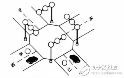
2. Control requirements for traffic lightsThe traffic light control schematic is shown in Figure 1.

Figure 1 Schematic diagram of traffic light control
Traffic light control requirements:
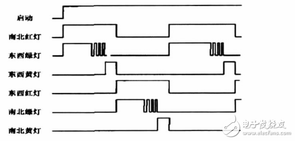
(1) The signal light is controlled by a start switch. When the start switch is turned on, the signal light system starts to work normally, and the south and south red lights are on, and the green light is on. When the start switch is turned off, all lights go out.
(2) The south-south red light is maintained for 25s, and the green light of the east and the west is also bright and remains for 20s. When it is 20s, the green light of the thing will shine, and it will go out after 3s. When the green light of the east and the earth is extinguished, the yellow light of the thing is bright and maintained for 2s. When it is 2s, the yellow light of the thing is extinguished, and the red light of the thing is bright; at the same time, the red light of the north and south is extinguished, and the green light of the north and south is bright.
(3) The red light of the thing is maintained for 30s, the green light of the north and south is maintained for 25s, then it is flashed for 3s and extinguished. At the same time, the yellow light of the north and south is bright, and it is extinguished after 2s. At this time, the red light is bright and the green light is bright.
(4) The above signal state is repeated.
3, system timing diagramAccording to the analysis of traffic signal control requirements, it is concluded that this is a sequential logic control system. First draw the timing diagram, which is convenient for the design of the system software and hardware. Figure 2 is the state timing diagram of the traffic light.

Figure 2 Status timing diagram of traffic lights
4, the system hardware designAccording to the control requirements, the Siemens S7-200 series PLC is used as the controller to meet the control requirements.
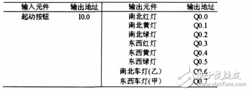
4.1. Assignment of PLCI/O pointsThe traffic light control system has one input point: the start button. The output signal has two sets of indicator driving signals in the east-west direction, the north-south direction, and the vehicle running indicator driving signal signals A and B in the east-west direction and the north-south direction. Since the indicators of the same color operate in the same direction in each direction, in order to save the number of output points, the parallel output method is adopted. It is thus determined that the number of input points required by the system is 1, and the number of output points is 8, all of which are switching quantities. The PLCI/O point assignment is shown in Table 1.
Table 1 PLCI/O point allocation

According to the system's demand for I/O port volume, the S7-200 is selected to complete the design. The hardware structure of the system is shown in Figure 3.

Figure 3 system hardware structure
Gunnpod Meta,Gunnpod 2000, Gunnpod air, gunnpod wave,gunn pod vape,Australia gunnpod,Gunnpod Meta
Nanning Nuoxin Technology Co., LTD , https://www.nx-vapes.com