The DMA (Direct Memory Access) controller is a unique peripheral that transfers data inside the system and can be thought of as a way to connect internal and external memory to each DMA-capable peripheral through a dedicated bus. Controller. It belongs to the peripheral because it is transmitted under the program control of the processor.
DMA controller features:8 independent channels, 4 can be used for PL-PS data management, each channel has 1024Byte MFIFO;
Data is transferred using the CPU_2x clock, CPU_2x = (CPU frq/6)*2;
Execute DMA instruction in the custom memory area to run DMA;
The AHB control register supports both secure and non-secure modes;
Built-in 4-word Cache for each channel;
The following mapped physical addresses of the SoC can be accessed:
DDR, OCM, PL, Linear QSPI Read, SMC and M_AXI_GP devices, the interconnection structure of the access device is shown in Figure 1.
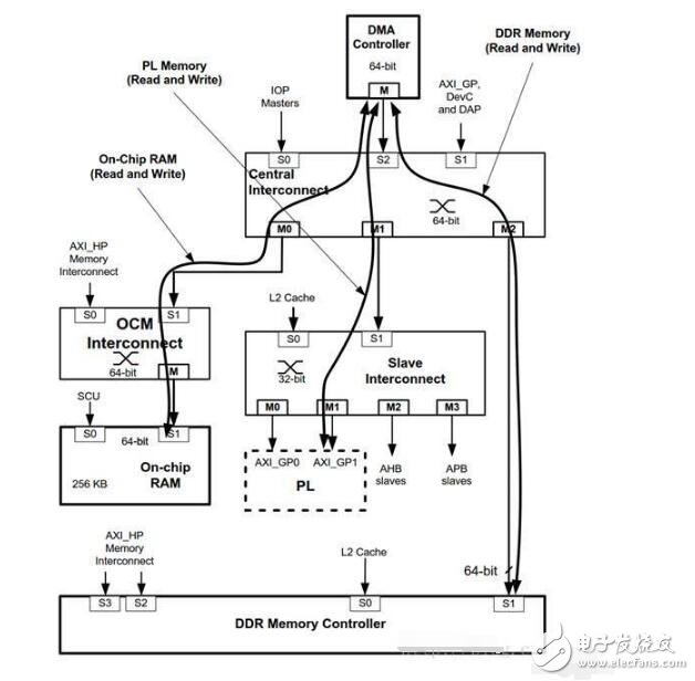
Figure 1
It can be seen from Figure 1 that the DMA controller can access all devices connected to the Central Interconnect and provides four channels of peripheral management interfaces for controlling the data handling of the PL.
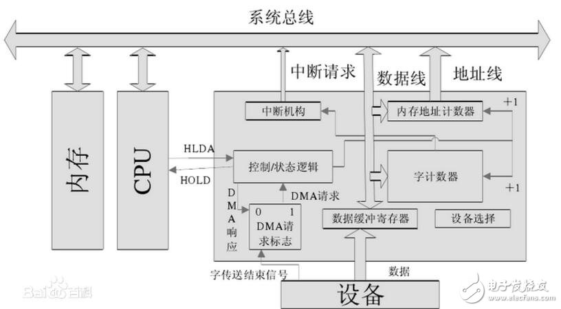
Dma controller consists of:A DMA controller is actually an interface circuit between a DMA-based peripheral device and a system bus. This interface circuit is composed of a DMA mechanism based on the interrupt interface. It is customary to refer to the DMA mode interface circuit as a DMA controller.
(1) Memory address counter: The address used to store the data to be exchanged in the memory. Before the DMA transfer, the data must be sent to the memory address counter by the program in the starting position (first address) in the memory. When the DMA transfers, the address counter is incremented by "1" every time the data is exchanged, thereby giving the address of a batch of data to be exchanged in the memory incrementally.
(2) Word counter: used to record the length of the transmitted data block (how many words). The content is also preset by the program before data transfer, and the number of words exchanged is usually expressed in complement form. At the time of DMA transfer, the word counter is incremented by "1" for each word transmitted. When the counter overflows, the highest bit generates a carry, indicating that the batch of data is transferred, thus causing the DMA controller to send an interrupt signal to the CPU.
(3) Data buffer register: used to temporarily store data (one word) for each transfer. When input, it is sent to the data buffer register by the device (such as a disk), and then sent to the memory by the buffer register through the data bus. Conversely, when outputting, the memory is sent to the data buffer register through the data bus and then sent to the device.
(4) DMA request" flag: A control signal is given every time the device prepares a data word to make "DMA"
The request flag is set to "1". When this flag is set, a DMA request is issued to the "control/status" logic, which in turn issues a bus usage right request (HOLD) to the CPU, and the CPU sends back a response signal HLDA in response to the request. The Control/Status logic receives this signal and issues a DMA response to reset the DMA Request flag in preparation for swapping the next word.
(5) Control/Status logic: consists of control and timing circuits and status flags, etc., used to modify the memory address counter and word counter, specify the transfer type (input or output), and the "DMA request" signal and CPU response signal. Coordinate and synchronize.
(6) Interrupt mechanism: When the word counter overflows, it means that a group of data is exchanged, the interrupt mechanism is triggered by the overflow signal, and an interrupt report is reported to the CPU.
The main role is to configure the DMA controller and start the corresponding transfer
The functions of the public DMA controller in s3c2440 are provided as follows:
S3c2410_dma_config()
S3c2410_dma_ctrl()
S3c2410_dma_enqueue()
S3c2410_dma_devconfig()
S3c2410_dma_set_buffdone_fn()
S3c2410_dma_request()
S3c2410_dma_free()
The general order of use is as follows:
Request = "set_buffdone_fn=" devconfig = " config = " enqueue = " ctrl = " free
1, int s3c2410_dma_request (unsigned int channel, struct s3c2410_dma_client *client, void *dev)
2, staTIc inline void s3c2410_dma_buffdone(struct s3c2410_dma_chan *chan, struct s3c2410_dma_buf *buf, enum s3c2410_dma_buffresult result)
Set the corresponding dma channel to complete a callback function after dma transmission
3, int s3c2410_dma_devconfig (int channel, enum s3c2410_dmasrc source, unsigned long devaddr)
Source: S3C2410_DMASRC_HW: source is hardware
S3C2410_DMASRC_MEM: source is memory
Devaddr: physical addr of source
4, int s3c2410_dma_config (unsigned int channel, int xferunit)
Set the channel's control register DCONx according to xferunit
Xferunit is the data size for each transfer: 0:byte 1:half word 2:word
5, dma_alloc_coherent
DMA requires non-cached, physical address contiguous memory.
The corresponding kernel virtual address is converted into a physical address and used by the latter s3c2410_dma_enqueue function.
6, int s3c2410_dma_enqueue (unsigned int channel, void *id, dma_addr_t data, int size)
7, int s3c2410_dma_ctrl (unsigned int channel, enum s3c2410_chan_op op)
8, int s3c2410_dma_free (unsigned int channel, struct s3c2410_dma_client *client)
DMA controller interface function use caseS3c2440 DMA datasheet
The s3c2440 DMA controller supports DMA transfers in four cases:
a. source and desTInaTIon are in the system bus
Source in the system bus while desTInation in the peripheral bus
Source in the peripheral bus while destination in the system bus
d. source and destination are in the peripheral bus
However, in the arch/arm/plat-s3c24xx/dma.c function s3c2410_dma_devconfig, only b and c are implemented.
S3c2440 has 4 DMA channels, each channel has DISC/DISCC/DIDST/DIDSTC register, DISC and DIST can be filled in different source types (refer to S3c2440 Datasheet Table 8-1 for details), in addition to filling in memory The physical address is used as source or destination.
3 parameters related to transmission:
TSZ: DCON [28], 0: unit mode: one transfer1 data size, burst mode: one transfer 4 data size
DSZ:DCON[21:20],0:data size is BYTE,1:data size is Half WORLD,0:data size is WORLD
TC:DCON[19:0], transfer count
The amount of data transferred = TC * (DSZ * 8) * TSZ
Request source: DCON[23]
0: S/W request mode, DMA is triggered by setting SW_TRIG bit of DMASKTRIG control register
1:DMA source selected by bit[26:24] triggers the DMA operation
Service mode:DCON[27]
0:single service mode, one DMA request completes an atomic operation, waiting for the next request
1:whole service mode, a DMA request completes a batch of atomic operations, when TC=0 means complete a whole service
Communication Backup Lithium Battery System
48V Dc Battery System,Lithium Battery System,Long Cycle Time Battery System,Communication Backup Battery System
Wolong Electric Group Zhejiang Dengta Power Source Co.,Ltd , https://www.wldtbattery.com