1. Power line noise
The electromagnetic disturbance generated by various electrical equipment in the power grid is caused by the propagation along the power line. The noise of the power line is divided into two categories: common mode interference and differential mode interference.
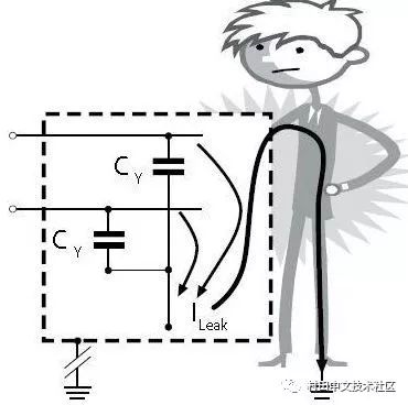
1. Common-mode Interference: The amplitude of the interference current on the two wires is equal, and the same direction is called common mode interference. (unwanted potential between any carrier fluid and ground)
Elimination of common mode interference
The common mode choke works as follows:
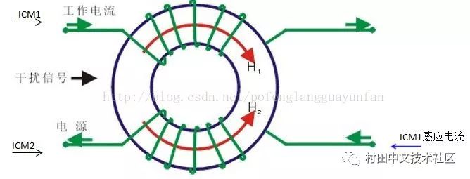
Common mode choke
When a normal current in the circuit passes, the current generates a reverse magnetic field in the in-phase wound inductor and cancels each other. At this time, the normal signal current is mainly affected by the coil resistance (and a small amount of damping due to leakage inductance); When the common mode current flows through the coil, due to the same direction of the common mode current, the same magnetic field is generated in the coil to increase the impedance of the coil, so that the coil exhibits a high impedance and a strong damping effect. Attenuating the common mode current for filtering purposes.
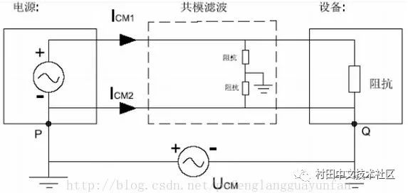
The working principle of the common mode capacitor and the working principle of the differential mode capacitor are the same. Both use the high frequency and low resistance of the capacitor to make the high frequency interference circuit short circuit, and the circuit is not affected at low frequency. Only the differential mode capacitor is a short circuit between the two poles, and the common mode capacitor is a line to ground short circuit.
Methods to eliminate common mode interference include:
(1). Use twisted pair and effectively ground.
(2). Where a strong electric field is required, it is also necessary to use a zinc tube shield.
(3). Keep away from the high voltage line during wiring, and do not bundle the high voltage power line and signal line together.
(4). Do not share the same power supply with the electronic control unit.
(5). Use linear power supply or high quality switching power supply (ripple interference less than 50mV)
(6). Using differential circuit
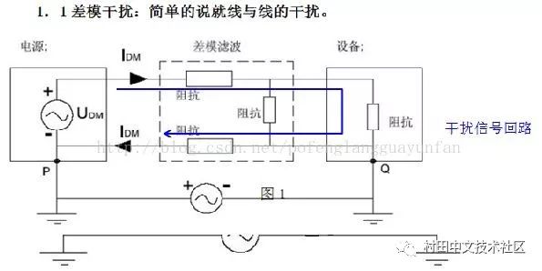
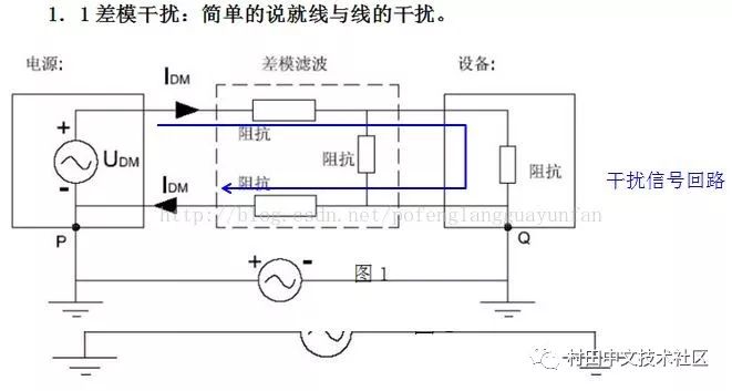
2. Differential-mode Interference: The interference current on the two wires has the same amplitude and the opposite direction is called differential mode interference. (unwanted potential difference between any two carrier fluids)
(Capacitor C has a capacity range of approximately 2200pF-0.1uF. To reduce leakage current, the capacitance should not exceed 0.1uF)
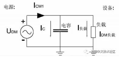
Elimination of differential mode interference
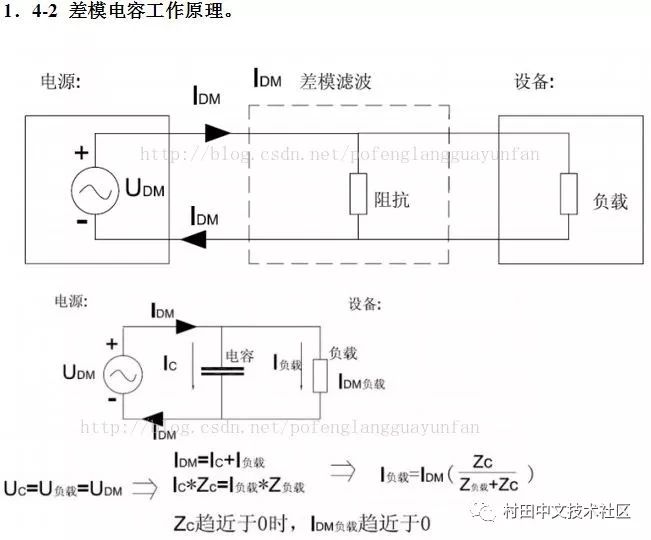
When the frequency of the interference signal is higher, the smaller the Zc, the more obvious the effect, and the circuit is not affected at all times. (The capacity of capacitor C is approximately 0.01-0.47uF)
Any interference signal transmitted on the power line is represented by differential mode and common mode signal. Differential mode interference is transmitted between two wires, which is a symmetrical interference; common mode interference is transmitted between the wire and the ground (chassis). Refers to the noise generated on the two signal lines with equal amplitude and phase, which belongs to non-symmetric interference. Under normal circumstances, the differential mode interference is small, the frequency is low, and the interference caused is small; the common mode interference amplitude is large, the frequency is high, and the radiation can be radiated by the wire, and the interference caused is small.
3. Filter
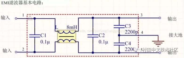
The five-terminal device has two inputs, two outputs and one ground, and the case should be connected to ground when in use.
L suppresses common mode interference and does not contribute to differential mode interference.
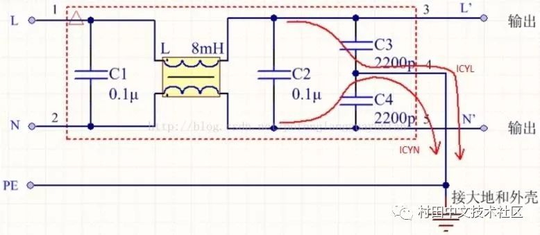
Two of the red lines are common mode interference current loops of the live and neutral lines N, called leakage current loops.
L is 220V with respect to N, and if the case is not grounded, there is a voltage of 110V.
Calculation of ground leakage current:
Icd=2*pi*f*C*Uc
Where Icd is the leakage current; f is the grid frequency;
Icd=ICYL+ICYN
=50*110*2*3.1415926*(2200p)*2
=0.15mA
The leakage current is proportional to C, so the safety is high (but C is too small, the leakage current is too small and can not eliminate the interference), usually several hundred microamperes to several milliamps.
The higher the resistance of the grounding wire, the greater the risk the user faces. If a person touches the device that is damaged by the grounding wire, the leakage current will flow through the human body to the ground.
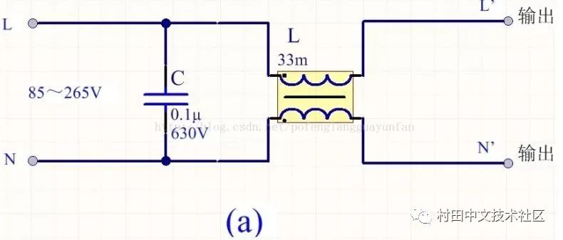
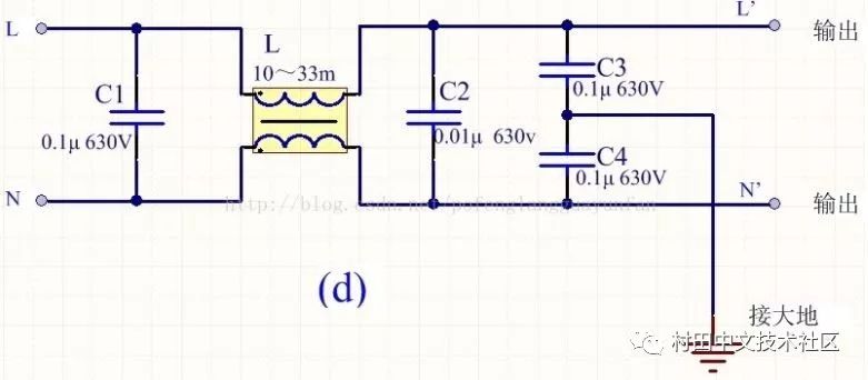
Four commonly used EMI devices
In order to reduce cost and reduce volume, switching power supplies generally use simple EMI filters, mainly including common mode choke L and filter capacitors. The following four types can be selected according to the situation:

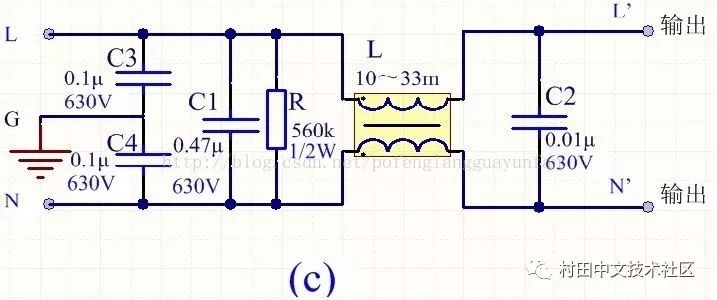
The above figure R is a discharge resistor, which can discharge the accumulated charge on C1, avoiding the influence of the charge accumulation and affecting the filter characteristics. After the power is turned off, the power supply terminal can be de-energized to ensure the safety of use.
2. Noise caused by input current distortion
Switching power supplies generally use bridge rectification, capacitive filtering devices. In the input stage without PFC function, due to the nonlinearity of the rectifier diode and the energy storage function of the filter capacitor, the conduction angle of the diode becomes smaller, and the input current becomes a spike current with a very high peak and a short time. Harmonic interference is introduced to the system and the power factor is reduced.
3. Interference caused by switching tubes and transformers
The switch tube is the core device of the switching power supply and is also the source of interference. When the frequency of the switching tube rises, the switching frequency of the switching tube rises, which will increase the interference to the whole system. At this time, if the parameters of the diode or capacitor resistance of the absorption circuit are improperly selected, the whole system will be disturbed.
During the working process of the switching power supply, a high-frequency current loop is formed by the primary filter large capacitor, the high-frequency transformer primary coil and the switch tube, and the loop causes a large radiation noise.
4. Noise generated by the output rectifier diode
The ideal diode is turned off when subjected to a reverse voltage and no reverse current is passed. In the actual diode, when the diode is forward-conducting, the charge of the PN junction is accumulated. When the diode is subjected to the reverse voltage, the charge of the PN junction is released and forms a reverse recovery current, which returns to the zero point and junction capacitance. The size is related. An RC can be connected in parallel across the diode to absorb noise.
V. Noise of switching power supply caused by distribution and parasitic parameters
The distributed parameter of the switching power supply is the intrinsic factor of most interference. The distributed capacitance between the switching power supply and the heat sink, the distributed capacitance between the primary and secondary of the transformer, and the leakage inductance of the primary and secondary sides are all noise sources, and in addition to the high frequency signal. The components have high frequency characteristics. When the high frequency is working, the wire becomes the emission line, the capacitance becomes the inductance, the inductance becomes the capacitance, and the resistance becomes the resonance circuit.
Machining Parts
Shaft sleeve connector
Shaft sleeve connector
Material: stainless 304
Surface: ultrasonic wave cleaning, passivating
Tube connector
Material: GB20
Surface: trivalent chromium zinc coating
Application: fixed end for control system assembly
Tube guide threaded
Material: stainless 304
Surface: ultrasonic wave cleaning, passivating
Application: control system in Yacht
Control Shaft,Tube Connector,Tube Guide Threaded,Shaft Sleeve Connector
ROYAL RANGE INTERNATIONAL TRADING CO., LTD , https://www.royalrangelgs.com