MAX2266 power amplifier with PIN diode switch for CDMA cellular band
Abstract: This article introduces the complete application circuit of the MAX2266 cellular CDMA power amplifier (PA), and provides detailed information of the PIN diode switch, and gives the output power, gain, ACPR, power efficiency (PAE) and idle mode Data such as power supply current. In low power mode (idle current is only 39mA), 15-16% PAE can be provided when the output power is + 15dBm; 11% PAE can be provided when the output power is + 13dBm.
The MAX2266 power amplifier is optimized for CDMA cellular phones based on IS-98 operating in the cellular band. The MAX2266 has optimized efficiency at medium power output. The result is lower average current consumption in typical urban environments and longer talk times.
The MAX2266 standard evaluation board uses a single-pole double-throw (SPDT) switch. This evaluation board has a PAE of 31% at + 28dBm output power and a PAE of 17% at + 16dBm output power. In this application, the PIN diode switch is used instead of the SPDT switch. The use of PIN diodes can achieve better power additional efficiency at maximum output power; in addition, the MAX2266 also has a good PAE at medium and low power output.
Alpha Industries' SMP1321-079 is used in this application. Figure 1 shows the principle diagram of the PIN diode switch. When the MAX2266 is in high power mode, SHDN = high, POW = high, and the PIN diode switches to OFF. At this time, POUT has high impedance. When the MAX2266 is in low power mode, SHDN = high, POW = low, and the PIN diode switches to ON.
L1 and L3 are choke coils, and L2 needs to form a parallel resonance with the capacitance inside the PIN diode. The forward current of the PIN diode is determined by R1. 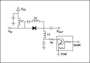
figure 1.
Figure 2 is the output matching section. If the low-power channel and the high-power channel are not connected, the performance of the MAX2266 is almost the same as the performance of the MAX2265. MAX2265 can achieve more than 37% PAE. Poorly isolated low-power channels can cause degradation of PAE and ACPR performance. In high-power mode, the low-power channel requires good isolation to obtain excellent performance in this mode. 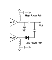
figure 2.
The performance is shown in Table 1. There are three cases of data: maximum output power (+ 28dBm), switching point (+ 15dBm) and medium output power (+ 14dBm). With a PIN diode switch, the PAE at maximum output power is improved because the isolation between the two outputs is increased. At maximum output power, ACPR over -45dBc and 35% PAE can be achieved. Medium output power, can achieve ACPR exceeding -46dBc and 15% PAE when outputting 15dBm; 11% PAE can be achieved when outputting 13dBm. The reactive current is 39mA.
Table 1
(VCC = 3.3V, input signal = CDMA standard signal)
| Frequency (MHz) | Gain (dB) | ACPR (885kHz) (dBc) | ACPR (1.98MHz) (dBc) | PAE (%) | Idle Current (mA) |
| High-Power Mode @ POUT = + 28dBm | |||||
| 824 | 26.72 | -45.53 | -56.03 | 34.45 | |
| 836 | 26.38 | -46.44 | -57.00 | 35.08 | 127 |
| 849 | 25.82 | -45.88 | -56.75 | 35.47 | |
| Low-Power Mode @ POUT = + 15dBm | |||||
| 824 | 27.82 | -45.92 | -61.23 | 15.70 | |
| 836 | 27.62 | -46.75 | -61.34 | 15.97 | 39 |
| 849 | 27.26 | -47.86 | -61.26 | 15.70 | |
| Low-Power Mode @ POUT = 13dBm | |||||
| 824 | 28.06 | -54.16 | -64.10 | 11.19 | |
| 836 | 27.80 | -54.91 | -64.99 | 11.19 | 39 |
| 849 | 27.42 | -54.65 | -62.84 | 11.19 | |
Assuming that the switching point from high-power mode to low-power mode is +15 dBm, Figures 3 and 4 are the results of actual work. In the CDMA system, PAE at medium output power is very important for the actual long-term conversation. If the MAX2266 is switched at + 15dBm, the PAE of medium output power will increase, and at the same time, the ACPR at this point is also less than -46dBc.
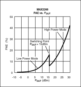 | 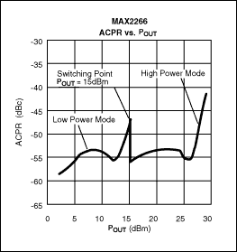 |
| image 3. | Figure 4. |
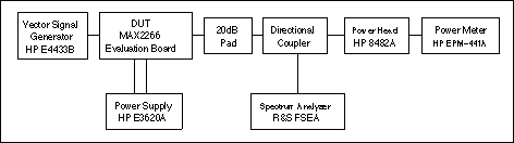
Figure 5. Test setup
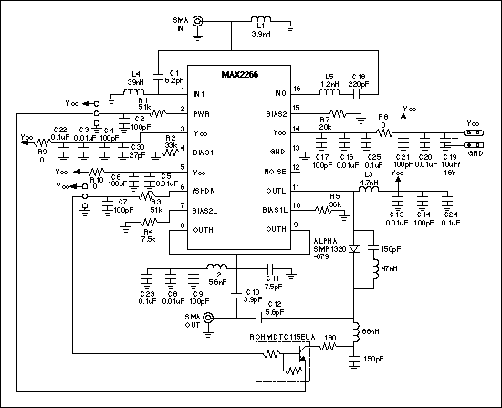
Figure 6. Schematic diagram
Wireless In Ear Earphone Tws Earbuds /Wireless Earbuds
Product Description
Features:
1, True wireless stereo: realizes movement and wireless control and everyone can share music without wrie
2, Comfortable and convenient: Earplug made of food-grade silica gel material in combinalion with the design to avoid falling off, which makes you comfortable and relieved,also the Earbuds can be Dual or Single use.
Specification
Bluetooth Version: Bluetooth 4.2+EDR
Voice prompt for calling number
Voice prompt for power and or off
Supports :A2DP1.3/HFP1.6/HSP1.2/AVRCP1.6/DI1.3
Adopt the advanced CVC6.0 active noise-cancellation
Built-in superior HD microphone, provide clear and loud sound
Selectable colors: black,,blue and Green
Tws Earbuds,Fully Wireless Earbuds,Wireless In Ear Headphones ,Mini Wireless Earbuds
Shenzhen Greater Industry Co., Ltd. , https://www.szgreater.net